
Engine pcv system with hydrophobic, oleophobic membrane for air/oil separation

a technology of air/oil separation and pcv system, which is applied in the direction of charge feed system, combustion engine, non-fuel substance addition to fuel, etc., can solve the problems of engine oil vapor and droplets being unusable, and achieve the effect of inhibiting the passage of oil

Inactive Publication Date: 2008-09-18
GM GLOBAL TECH OPERATIONS LLC
View PDF9 Cites 26 Cited by
  • Summary
  • Abstract
  • Description
  • Claims
  • Application Information

AI Technical Summary

Benefits of technology

[0004]The present invention provides a crankcase emission control system for an internal combustion engine that utilizes a hydrophobic, oleophobic membrane to separate oil droplets from the crankcase vapors before the crankcase vapors exit the crankcase. The membrane allows air and other vapors to pass but separates the oil droplets out for return to the crankcase thus reducing oil loss through the crankcase emission control system. The hydrophobic, oleophobic membrane may be used in place of or may supplement conventional air / oil separation arrangements used in crankcase emission control systems such as PCV systems. The membrane is also capable of preventing water vapor from passing, thereby reducing the possibility of throttle body icing that may occur due to cold (i.e., at or below freezing) air intake conditions.
[0006]In a further embodiment, the present invention provides an internal combustion engine including a crankcase and at least one cylinder. A cylinder air intake system is in fluid communication with each cylinder. A crankcase air outlet connects the crankcase to the cylinder air intake system to allow crankcase vapors to be drawn into the inlet air passing to the cylinders. A hydrophobic, oleophobic membrane covers the crankcase air outlet. The membrane inhibits the passage of oil and water out of the crankcase through the crankcase air outlet.

Problems solved by technology

It is undesirable for engine oil vapors and droplets to be entrained in the crankcase vapors that are passed to the intake air system.

Method used


Image

  • Engine pcv system with hydrophobic, oleophobic membrane for air/oil separation
  • Engine pcv system with hydrophobic, oleophobic membrane for air/oil separation
  • Engine pcv system with hydrophobic, oleophobic membrane for air/oil separation

Examples


Embodiment Construction

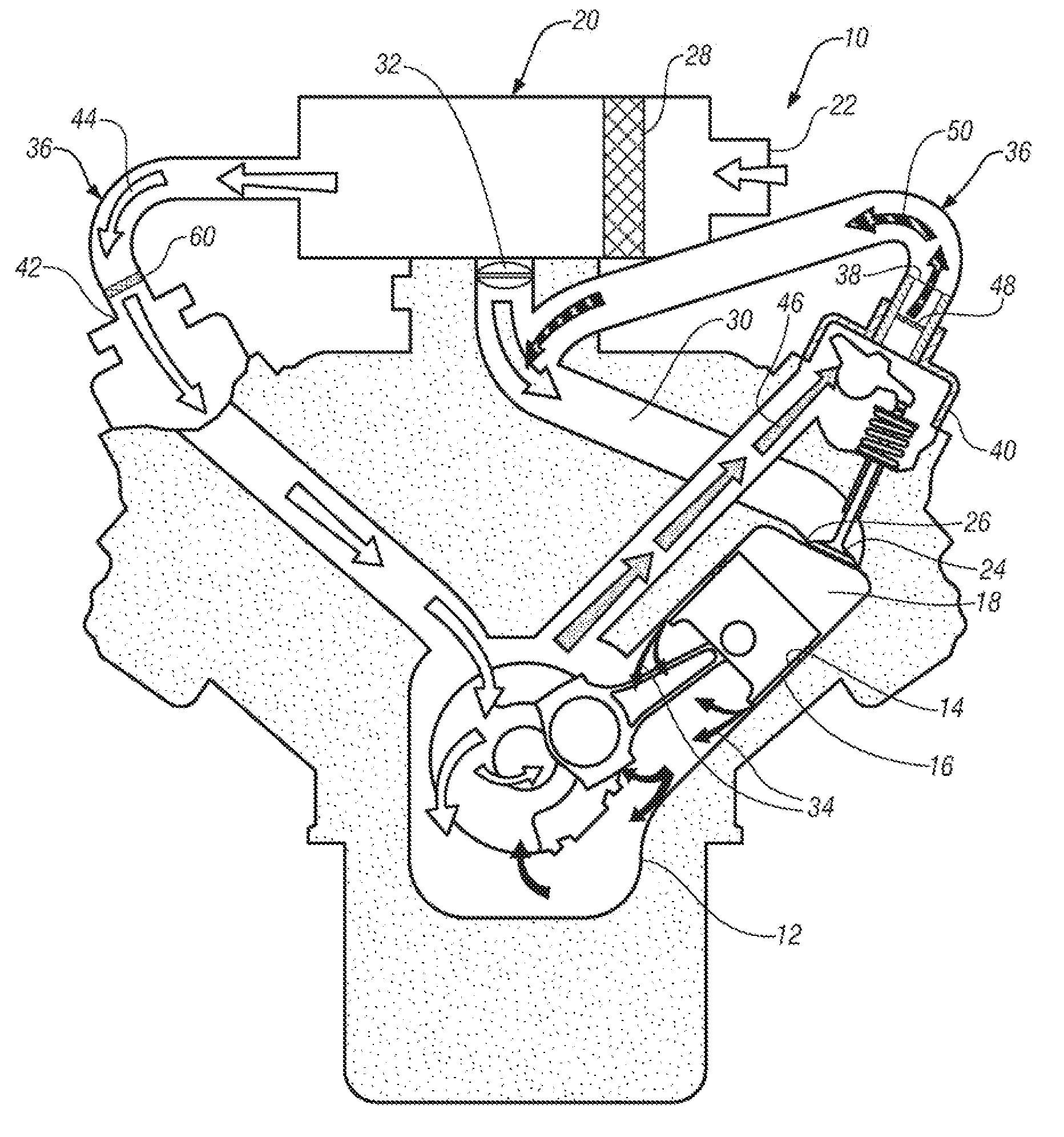
[0011]Referring now to the drawings in detail, numeral 10 generally indicates an internal combustion engine in accordance with the present invention. The internal combustion engine 10 may generally be either a gasoline engine or a diesel engine. The engine 10 generally includes a crankcase 12 and at least one cylinder 14. A piston 16 is reciprocable in each cylinder 14 and defines a variable volume combustion chamber 18 therein.

[0012]A filtered cylinder air intake system 20 is in fluid communication with each combustion chamber 18. The cylinder air intake system 20 generally extends from a fresh air inlet 22 to cylinder intake valves 24 located in cylinder intake ports 26. The cylinder air intake system 20 may include an air filter 28 and an air intake manifold 30. A throttle 32 may also be disposed in the cylinder air intake system 20 for controlling cylinder intake airflow to the associated cylinders 14. The cylinder air intake system 20 may alternatively be referred to as an air ...


PUM


Abstract

An engine crankcase emission control system for an internal combustion engine includes a cylinder air intake system connected to associated engine cylinders. The system also includes an engine crankcase. A crankcase air outlet connects the crankcase to the cylinder air intake system at a location subject to variable intake vacuum pressures to allow crankcase vapors to be drawn into inlet air passing to the cylinders. A hydrophobic, oleophobic membrane covers the crankcase air outlet. The membrane inhibits the passage of oil and water out of the crankcase through the crankcase air outlet.

Description

TECHNICAL FIELD[0001]This invention relates to internal combustion engine crankcase emission control systems, and more particularly to air / oil separation in crankcase emission control systems.BACKGROUND OF THE INVENTION[0002]It is known in the art relating to internal combustion engines to use a crankcase emission control system, such as a positive crankcase ventilation (PCV) system, to remove crankcase vapors (including unburned fuel and combustion products that leak past the piston rings, oil vapors, and other vapors present in the crankcase) from the crankcase. To prevent excessive pressure in the crankcase and the buildup of combustion byproducts, PCV systems evacuate the crankcase vapors from the crankcase into the engine cylinder intake air system so that the crankcase vapors are burned in the engine combustion process. It is undesirable for engine oil vapors and droplets to be entrained in the crankcase vapors that are passed to the intake air system. Therefore, many PCV syst...

Claims


Application Information

Patent Timeline
IPC IPC(8): F02B29/00
CPCF01M13/022F01M13/023F01M13/04F01M2013/0438Y02T10/121F02M25/06F02M35/1019F02M35/10222F01M2013/0461Y02T10/12
Inventor HOMMES, DANIEL J.SPIX, THOMAS A.
Owner GM GLOBAL TECH OPERATIONS LLC
Features
  • Generate Ideas
  • Intellectual Property
  • Life Sciences
  • Materials
  • Tech Scout
  • Unparalleled Data Quality
  • Higher Quality Content
  • 60% Fewer Hallucinations
Learn More