Linear Optic Light Coupler

a technology of light couplers and optics, applied in the field of high coupling efficiency illumination systems, can solve the problems of large loss of light generated, large loss of light, and inability to capture the amount of light needed for bright lighting applications

Inactive Publication Date: 2008-09-18
FORD GLOBAL TECH LLC
View PDF1 Cites 38 Cited by
  • Summary
  • Abstract
  • Description
  • Claims
  • Application Information

AI Technical Summary

Benefits of technology

[0003]The present invention relates to a lighting or illumination assembly and system. More particularly, the present invention relates to a high coupling efficiency illumination system including a plurality of light sources.

Problems solved by technology

However, in certain applications, such as in swimming pool lighting, the final light output may be required to be placed in environments in which electrical contacts are undesirable.
Additionally, in yet other applications, limitations in physical space, accessibility, or design considerations may require that the light source be placed in a location different from where the final illumination is required.
The present methods are very inefficient with approximately 70% loss of the light generated in some cases.
In multiple fiber systems, these losses may be due to the dark interstitial spaces between fibers in a bundle and the efficiencies of directing the light into the fiber bundle.
In single fiber systems, a single fiber having a large enough diameter to capture the amount of light needed for bright lighting applications becomes too thick and loses the flexibility to be routed and bent in small radii.
Also, some laser diodes are expensive to utilize since they require stringent temperature control (e.g., the need for using thermoelectric coolers, and the like) due to the heat they generate in operation.
In addition, a concentrated array of packaged LEDs can lead to problems in the area of thermal management.

Method used


Image

  • Linear Optic Light Coupler
  • Linear Optic Light Coupler
  • Linear Optic Light Coupler

Examples


Embodiment Construction

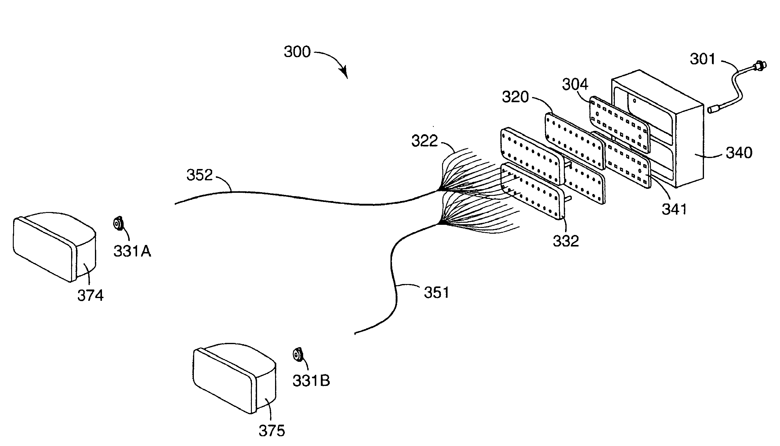
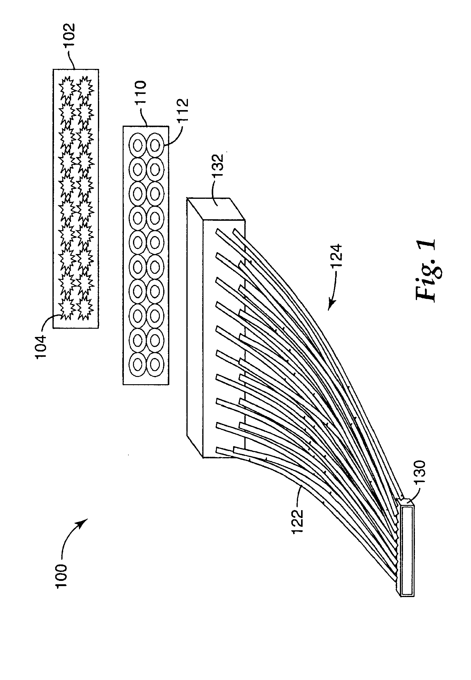
[0037]Generally, previous optical fiber lighting designs suffered from high coupling losses and were therefore very inefficient. An illumination system in accordance with the present invention provides for substantially higher light coupling efficiency. Furthermore, the illumination system of the present invention offers an incoherent light output that can appear to the human observer as arising from a single point of light. In addition, exemplary embodiments of the present invention show that an array of LED dies can be utilized to provide a high density, remote source of light that can be output at one or more locations. Moreover, exemplary embodiments of the present invention provide an array of LED dies that can be utilized to provide a high density, remote source of light that can produce one color, or multiple colors, either individually, or simultaneously, at one or more locations. In addition, the colors or color combinations of the source may be made changeable to suit part...


PUM


Abstract

An illumination system includes a plurality of radiation generating sources, such as LED dies. A corresponding plurality of optical waveguides is also provided, with each waveguide having a first and a second end, with each first end being in optical communication with the corresponding LED die. An array of corresponding passive optical elements is interposed between the plurality of LED dies and the corresponding first ends of the plurality of optical waveguides. The illumination system provides for substantially high light coupling efficiency and an incoherent light output that can appear to the human observer as arising from a single point of light. In addition, the light can be output remotely at one or more locations and in one or more directions.

Description

RELATED APPLICATIONS[0001]The present application is related to U.S. patent application Ser. No. 10 / 726,222 entitled “Illumination System Using a Plurality of Light Sources”, which is incorporated by reference herein in its entirety.BACKGROUND OF THE INVENTION[0002]1. Field of the Invention[0003]The present invention relates to a lighting or illumination assembly and system. More particularly, the present invention relates to a high coupling efficiency illumination system including a plurality of light sources.[0004]2. Background Art[0005]Illumination systems are used in a variety of applications. Home, medical, dental, and industrial applications often require light to be made available. Similarly, aircraft, marine, and automotive applications require high-intensity illumination beams.[0006]Traditional lighting systems have used electrically powered filament or arc lamps, which sometimes include focusing lenses and / or reflective surfaces to direct the produced illumination into a b...

Claims


Application Information

Patent Timeline
Patent Type & Authority Applications(United States)
IPC IPC(8): F21V8/00
CPCG02B6/0008
Inventor DASSANAYAKE, MAHENDRAWASILEWSKI, ALFRED
Owner FORD GLOBAL TECH LLC
Why Eureka
Try Eureka