
Communication Resource Allocation Method of Base Station

Inactive Publication Date: 2008-09-18
ELECTRONICS & TELECOMM RES INST
View PDF12 Cites 14 Cited by
  • Summary
  • Abstract
  • Description
  • Claims
  • Application Information

AI Technical Summary

Benefits of technology

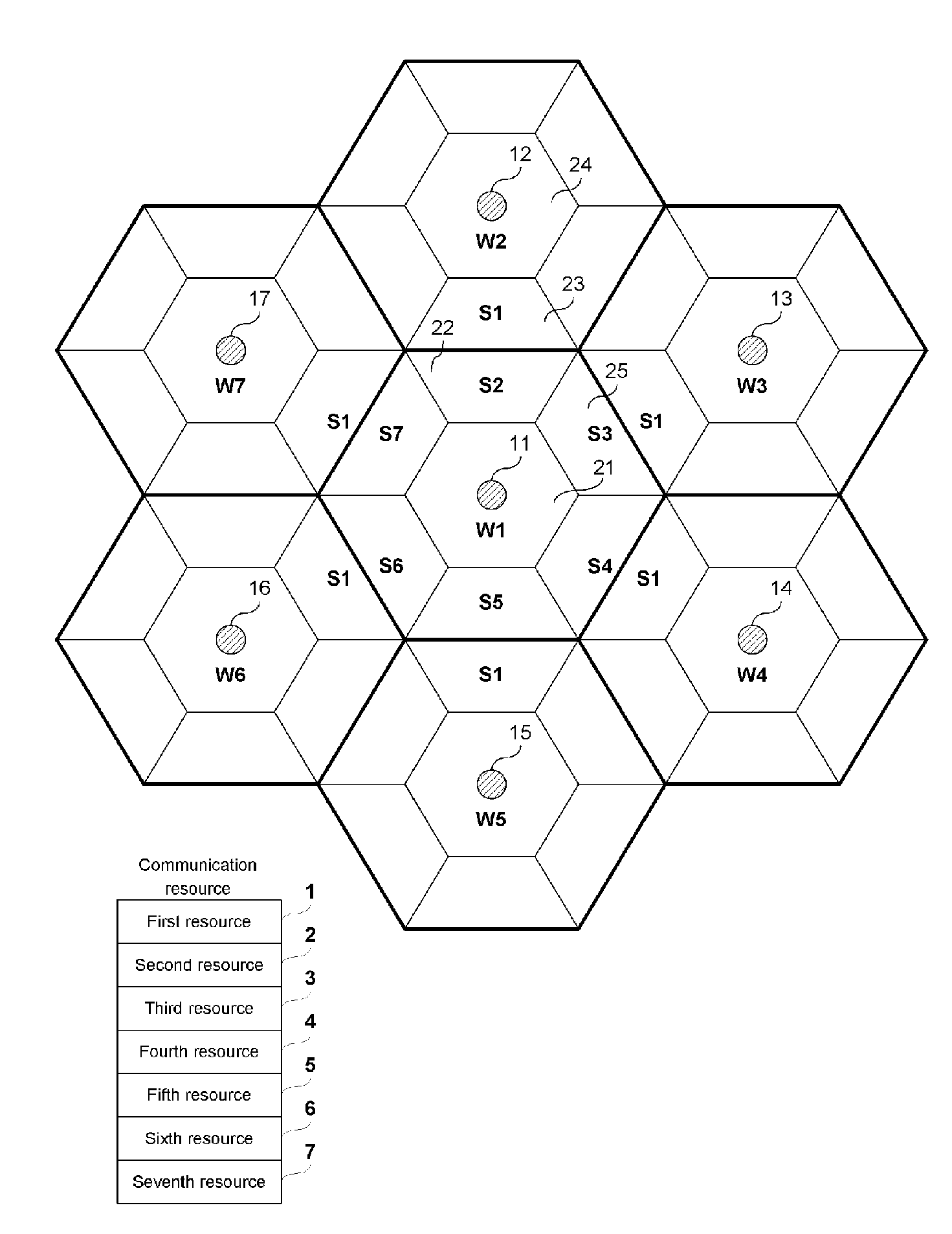
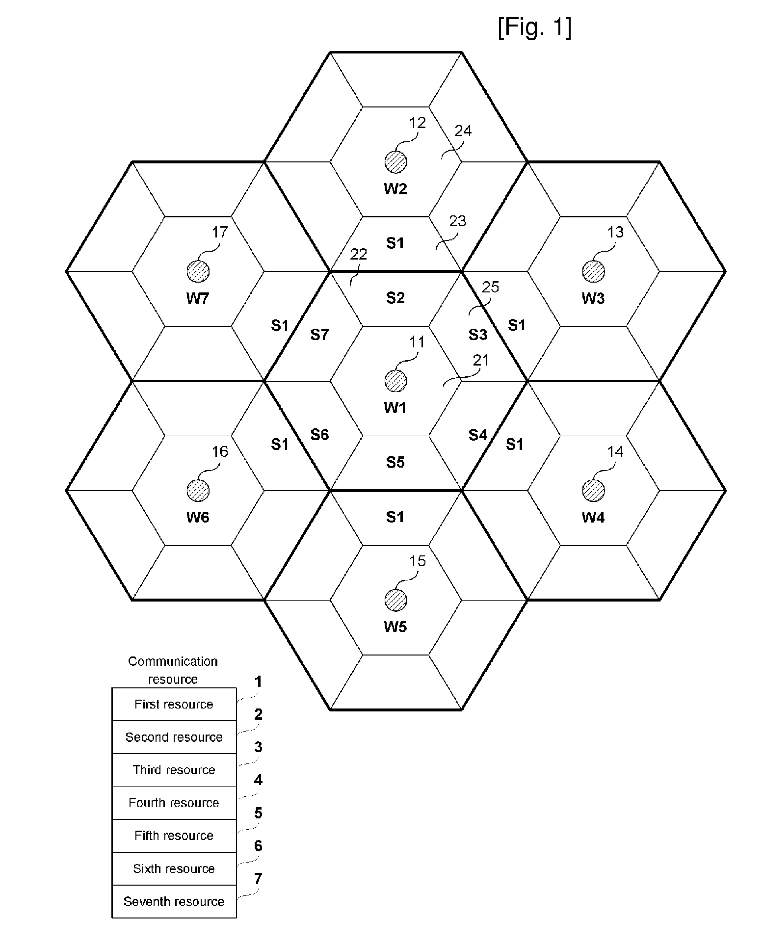
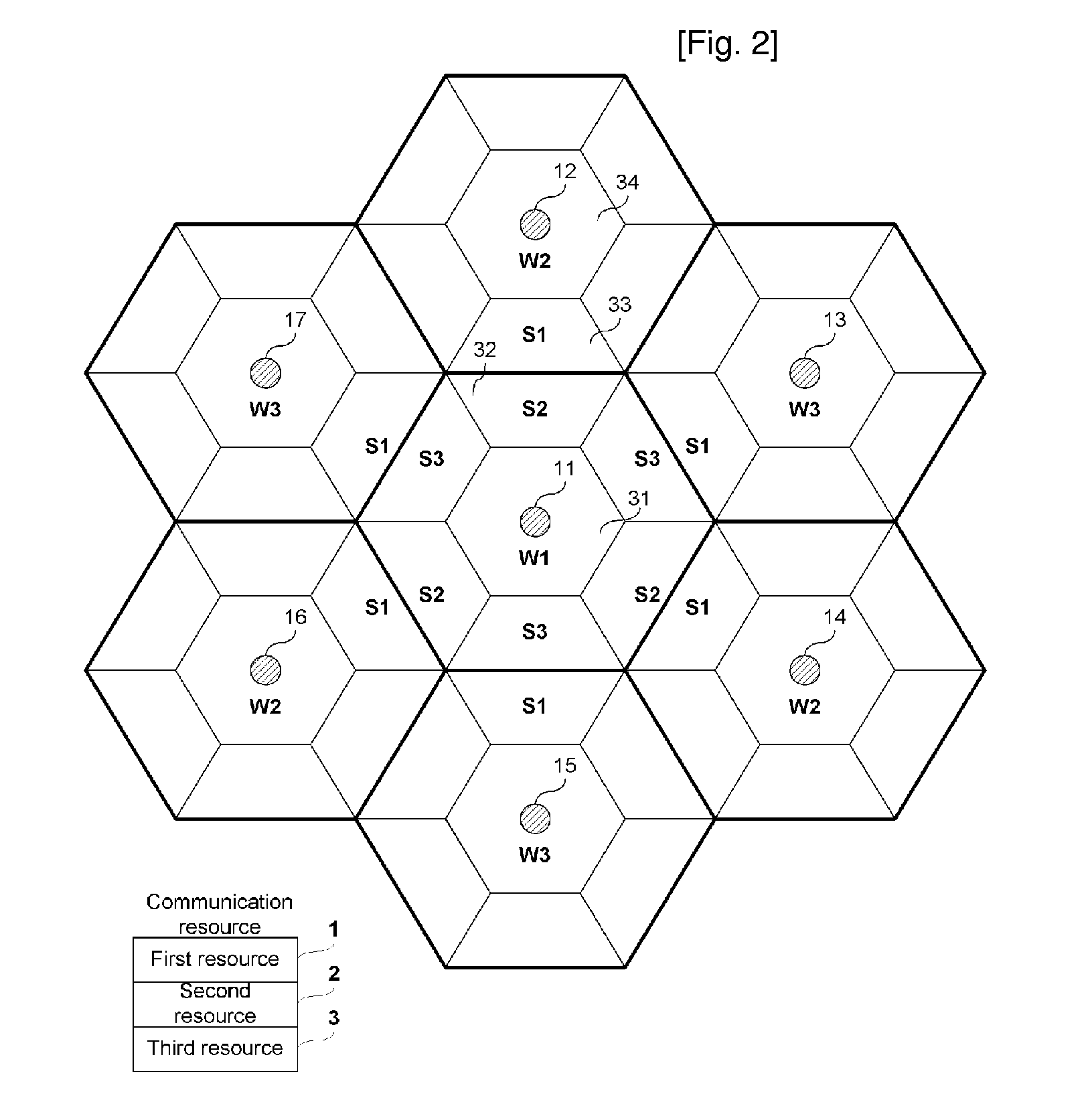
[0013]Yet another embodiment of the present invention provides a communication resource allocation method in which a first base station allocates a communication resource. The communication resource allocation method includes allocating a whispering resource to a whispering area, the whispering resource being a part of the communication resource and the whispering area being a peripheral area of the first base station; allocating a speaking resource corresponding to a whispering resource of a second base station to a speaking area, the speaking area being included in the first base station and being a border area between the first and second base stations; and increasing a ratio of the allocated whispering resource of the whispering area when the resource request of the whispering area is increased.
[0014]Yet another embodiment of the present invention provides a communication resource allocation method in which a first base station allocates a communication resource. The communication resource allocation method includes obtaining a path loss difference value, the path loss difference value being a difference between the first and second path loss values respectively between the first base station and the terminal and between the second base station and the terminal; allocating a first resource to a whispering area in which the path loss difference value is greater than a predetermined threshold value, the first resource being a part of the communication resource; allocating a second resource to a speaking area in which the path loss difference value is less than the predetermined threshold value, the second resource being a whispering resource of the second base station; and decreasing the threshold value when the resource request of the speaking area is increased.
[0016]Yet another embodiment of the present invention provides a communication resource allocation method in which a first base station allocates a communication resource. The communication resource allocation method includes allocating a whispering resource to a whispering area, the whispering resource being a part of the communication resource and the whispering area being a peripheral area of the first base station; allocating a speaking resource corresponding to a whispering resource of a second base station to a speaking area, the speaking area being included in the first base station and being a border area between the first and second base stations; decreasing a ratio of a second speaking resource corresponding to the whispering resource of the third base station when the resource request of the speaking area is increased; and increasing the ratio of the first speaking resource by the decrease of the ratio of the second speaking resource.

Problems solved by technology

However, when the adjacent cells use no common resource, the frequency reuse efficiency is decreased.
However, as a communication service is converted from a voice service of a constant data rate to a packet service of a changeable data rate, it is known that it is not optimal to maintain the appropriate interference by the interference averaging.
Also, as orthogonal frequency division multiplexing (OFDM) and orthogonal frequency division multiplexing access (OFDMA) technologies in which it is easy to avoid interference have been developed in cellular areas, an interference processing problem of adjacent cells has again occurred.
However, this method is not effective with regard to resource efficiency.
Particularly, according to the communication resource allocation method of the base station described above, the base station continuously allocates some specified communication resource to the terminal, and accordingly the terminal have a loss of a diversity gain.
Also, the communication resource allocation method described above may not solve inter-cell resource request imbalance content.

Method used


Image

  • Communication Resource Allocation Method of Base Station
  • Communication Resource Allocation Method of Base Station
  • Communication Resource Allocation Method of Base Station

Examples


Embodiment Construction

[0033]In the following detailed description, only certain exemplary embodiments of the present invention have been shown and described, simply by way of illustration. As those skilled in the art would realize, the described embodiments may be modified in various different ways, all without departing from the spirit or scope of the present invention. Accordingly, the drawings and description are to be regarded as illustrative in nature and not restrictive. Like reference numerals designate like elements throughout the specification.

[0034]When it is described that an element is coupled to another element, the element may be directly coupled to the other element or coupled to the other element through a third element.

[0035]Hereinafter, frequency, time, and code or the like used to perform a communication between the terminal and the base station is referred to as “a communication resource”.

[0036]Considering a propagation environment, the base station-peripheral area is referred to as “...


PUM


Abstract

A communication resource allocation method for solving resource request imbalance content in a cell is provided. Considering a propagation environment, the base station allocates a whispering resource to a whispering area, the whispering resource being one part of the communication resource and the whispering area being a peripheral area of the first base station, and allocates a speaking resource to a speaking area, the speaking resource being other parts of the communication resource and the speaking area being a border area of a cell. When the resource request of the whispering area is increased, the base station further allocates a part of the speaking resource to the whispering area or increases a ratio of the whispering resource. When the resource request of the speaking area is increased, the base station controls a threshold value for identifying the whispering and speaking areas or increases a ratio of the speaking resource.

Description

TECHNICAL FIELD[0001]The present invention relates a communication resource allocation method of a base station.BACKGROUND ART[0002]In order to avoid interference between adjacent cells, a conventional FDMA or TDMA-based cellular system may obtain a significant signal to interference ratio when the adjacent cells use no common resource. However, when the adjacent cells use no common resource, the frequency reuse efficiency is decreased. The conventional cellular system has a primary aim to provide a voice service of which a data rate is practically constant. Accordingly, it is effective for the cellular system to increase the number of available channels having the significant signal to interference ratio by means of power control so as to have increased system capability. Accordingly, a CDMA-based voice system that largely increases the frequency reuse efficiency has spread. The CDMA-based voice system allows a large of channels to have appropriate interference by decreasing a rang...

Claims


Application Information

Patent Timeline
IPC IPC(8): H04L12/28H04W16/02H04W16/30H04W72/08
CPCH04W16/02H04W72/08H04W72/048H04W72/54H04W72/51
Inventor KWON, JAE-KYUNAHN, JAE-YOUNGLEE, HYO-JINLEE, HEE-SOO
Owner ELECTRONICS & TELECOMM RES INST
Learn More