

Needle venting device for sealed containers
a technology of sealing ring and needle, which is applied in the direction of liquid handling, packaging goods, laboratory glassware, etc., can solve the problems of product (tube and cap) approximately 10 times the cost, leakage problems, and potential contamination of not only the added o-ring elastomer used as sealing ring in the cap, and achieve the effect of reducing manufacturing costs and increasing the effectiveness of sample containmen
- Summary
- Abstract
- Description
- Claims
- Application Information
AI Technical Summary
Benefits of technology
Problems solved by technology
Method used
Image

Examples
Embodiment Construction
, Detailed Description and Drawings.
SUMMARY OF THE INVENTION
[0024]Accordingly to the invention, the problems mentioned above are solved by cap closures that increase the effectiveness of sample containment and withdrawal at a reduced manufacturing cost.
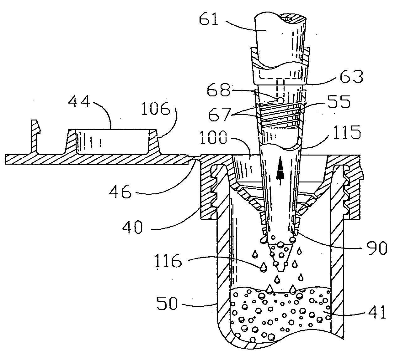
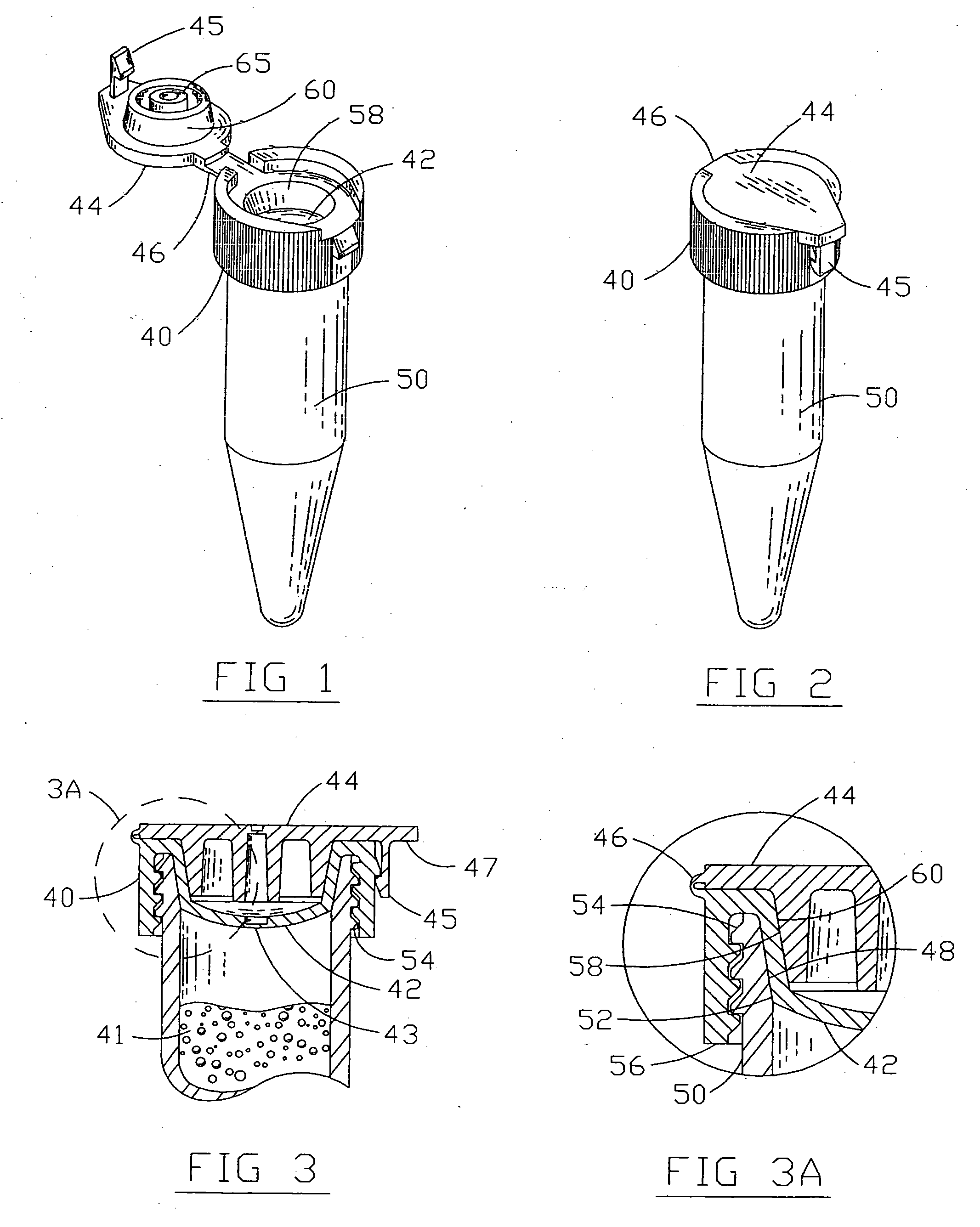
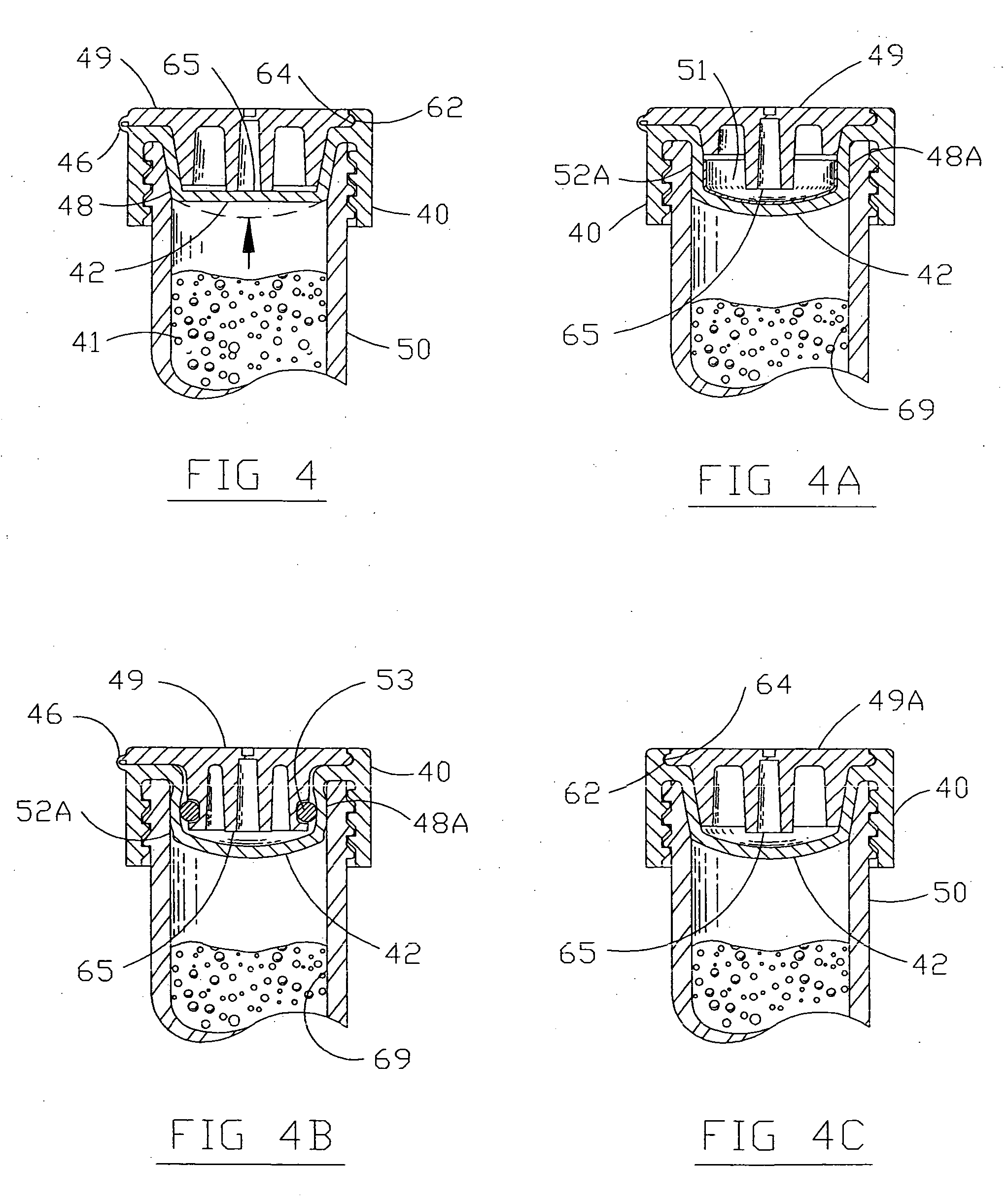
[0025]The present invention provides for a threaded cap design that incorporates a pressure responsive diaphragm that increases the sealing effectiveness of the cap when the internal pressures of the container increase during testing or storage (i.e.: centrifation, heating and freezing). As an improvement to “Sealing Cap for Containers” U.S. Pat. No. 5,513,768, the cap and the container have seamless matting tapered surfaces which increases the sealing contact area as the closure is screwed onto the container and promotes an effective seal. Using the mechanical advantage of the threads to compress the tapered side walls of the caps convex sealing diaphragm, the interference between the cap and its container increases as the cap is rot...
PUM
| Property | Measurement | Unit |
|---|---|---|
| depths | aaaaa | aaaaa |
| size | aaaaa | aaaaa |
| pore size | aaaaa | aaaaa |
Abstract
Description
Claims
Application Information