
Measurement system for correcting overlay measurement error

a measurement system and overlay technology, applied in the field of measurement systems, can solve the problems of difficult to freely vary the number or position of shots to be measured in a production line, relatively few attempts have been made to optimize the number or position of shots to be measured, and difficult to use such an experimental method in a variety of processes and conditions

Active Publication Date: 2008-09-18
KOREA ADVANCED INST OF SCI & TECH +1
View PDF10 Cites 34 Cited by
  • Summary
  • Abstract
  • Description
  • Claims
  • Application Information

AI Technical Summary

Benefits of technology

[0017]The present invention provides a measurement system that can obtain a measurement value close to a true value considering an overlay alignment error according to a high order regression analysis model.
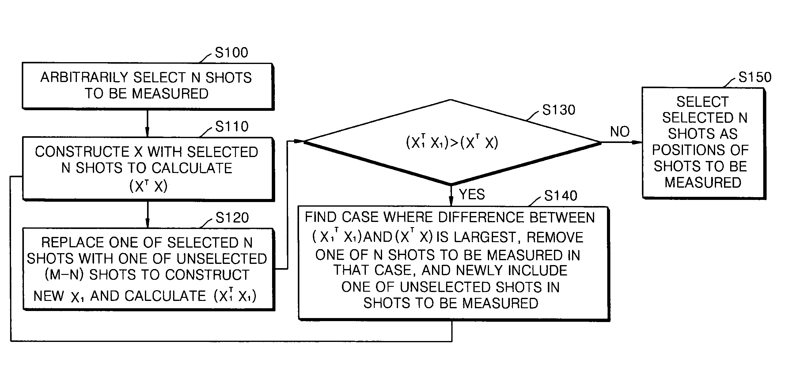
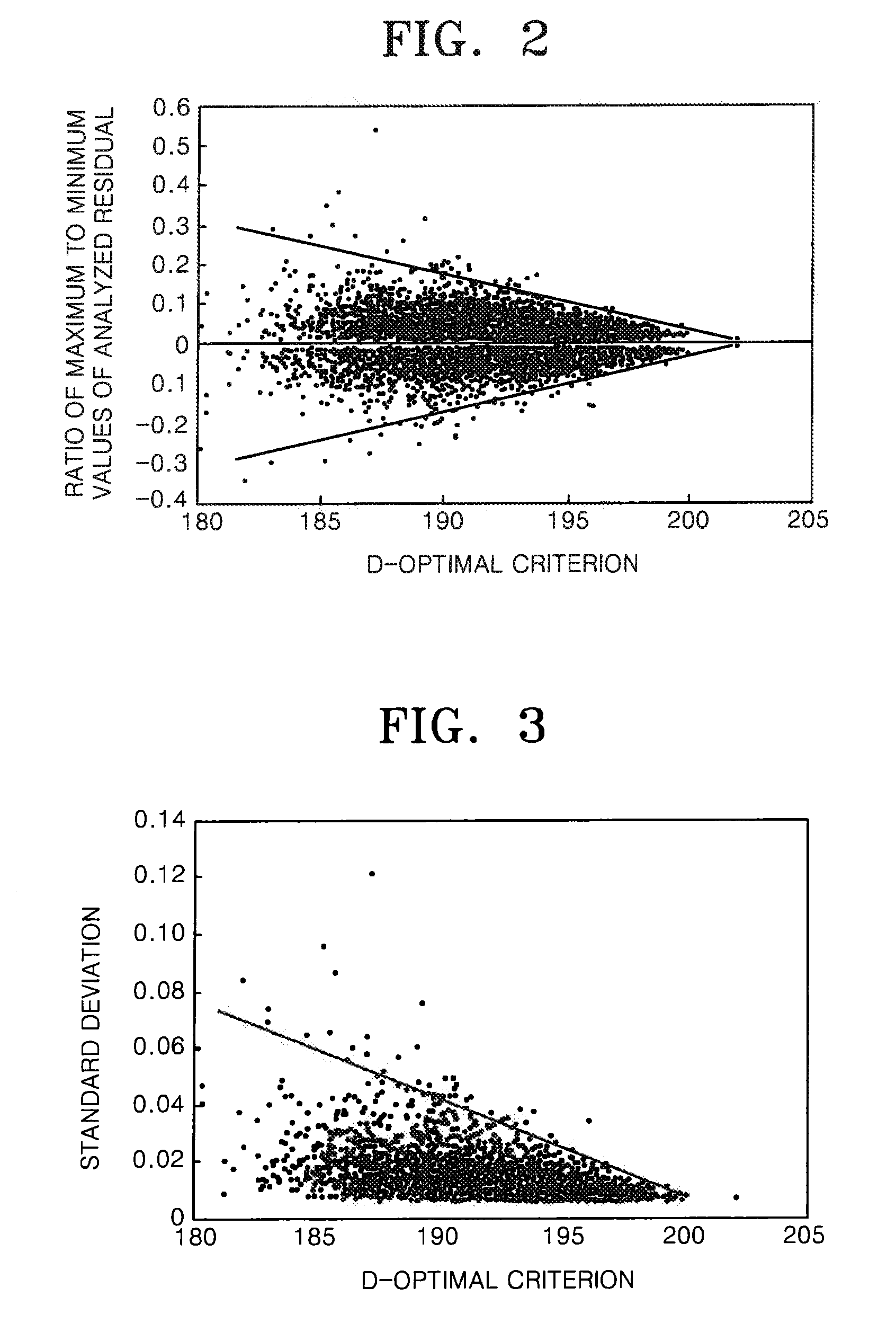
[0020]The optimal criterion may be a D-optimal criterion, an A-optimal criterion, a G-optimal criterion, or a V-optimal criterion that minimizes the size of a confidence interval of an estimate of a regression coefficient given in the function for the second or higher order regression analysis model.

Problems solved by technology

Accordingly, the conventional equipment systems for measuring the overlay alignment error are very difficult to freely vary the number or positions of shots to be measured in a production line.
However, in the case of the first order regression analysis model, the number or positions of shots to be measured do not greatly affect the reliability of analysis results.
Therefore, relatively few attempts have been made to optimize the number or positions of shots to be measured.
However, it is difficult to use such an experimental method in a variety of processes and conditions.
As semiconductor devices continue to shrink in size, an overlay alignment error to be measured becomes smaller.
Accordingly, analysis results obtained by a first order regression analysis model can no longer satisfy accuracy sufficient for correction of an overlay alignment error.
In the case of the high order regression analysis model, the number and positions of shots to be measured greatly affect the reliability of analysis.
That is, when the reliability of analysis necessary for accurate correction of an overlay alignment error is fixed and a semiconductor manufacturing process is stably performed, the number of shots to be measured necessary to obtain the reliability of analysis is relatively small, but when the reliability of analysis is fixed and a semiconductor manufacturing process is unstably performed, the number of shots to be measured to obtain the reliability of analysis is relatively large.
Accordingly, when the erroneous data is directly used in regression analysis without being filtered, analysis results are greatly distorted.
The distortion drastically reduces the accuracy of the correction of overlay alignment errors for subsequent lots.
The erroneous data may be caused when overlay marks are damaged due to particles on a wafer during operation or due to other processing.
That is, after regression analysis, when data has a size or a residual, which is unusually larger than that of other data, the data is detected as erroneous data.
However, it is possible that a method for detecting erroneous data using a least squares method fails to detect the erroneous data, or mistakes normal data for the erroneous data and removes the normal data.
The normal data mistaken for the erroneous data may distort estimates of overlay alignment errors for shots around measured shots.
Accordingly, accurate data cannot be obtained using only the conventional method for detecting erroneous data.

Method used


Image

  • Measurement system for correcting overlay measurement error
  • Measurement system for correcting overlay measurement error
  • Measurement system for correcting overlay measurement error

Examples


Embodiment Construction

[0044]The present invention will now be described more fully with reference to the accompanying drawings, in which exemplary embodiments of the invention are shown. While the present invention has been particularly shown and described with reference to exemplary embodiments thereof using specific terms, the embodiments and terms have been used to explain the present invention and should not be construed as limiting the scope of the present invention defined by the claims. Accordingly, it will be understood by those of ordinary skill in the art that various changes in form and details may be made therein without departing from the spirit and scope of the present invention as defined by the following claims. Like reference numerals denote like elements throughout.

[0045]The embodiments of the present invention provide a measurement system, which can obtain a measurement value considering an overlay measurement error according to a high order regression analysis model, and a measurement...


PUM


Abstract

A measurement system and a measurement method, which can obtain a measurement value close to a true value considering an overlay measurement error according to a higher order regression analysis model. The measurement system and the measurement method provide a technique for determining optimal positions of shots to be measured using an optimal experimental design. When the regression analysis model and the number of shots to be measured are determined in advance, a method is used for determining an optimal number of shots to be measured according to the regression analysis model and process dispersion using a confidence interval estimating method. A dynamic sampling method is used for dynamically changing the number and positions of shots to be measured according to a change in process features by combining the above two methods. And, when erroneous data is detected, or when measured data is missing, a robust regression analysis method and a technique for filtering the erroneous data and the missing data are used.

Description

CROSS-REFERENCE TO RELATED PATENT APPLICATION[0001]This application claims the benefit of Korean Patent Application No. 10-2007-0025142, filed on Mar. 14, 2007, in the Korean Intellectual Property Office, the disclosure of which is incorporated herein in its entirety by reference.BACKGROUND OF THE INVENTION[0002]1. Field of the Invention[0003]The present invention relates to a measurement system, and more particularly, to a measurement system for accurately obtaining an overlay alignment error for a non-measured shot using a high order regression analysis model.[0004]2. Description of the Related Art[0005]Measurement systems used for the characterization of semiconductor devices and the like measure various quantities. For example, a photolithographic process, which is essential for the manufacture of semiconductor devices, repeatedly transfers the same pattern onto a chemical material deposited on a wafer. In general, a pattern region to be exposed by a single exposure is called a ...

Claims


Application Information

Patent Timeline
IPC IPC(8): G06F11/00
CPCG03F7/705G03F7/70633G03F7/70508
Inventor LEE, MOON-SANGYUM, BONG-JINKIM, HONG-SEOKKIM, KWAN-WOOKIM, SEUNG-HYUNPARK, CHAN-HOON
Owner KOREA ADVANCED INST OF SCI & TECH
Learn More