Electric power generation method using thermoelectric power generation element, thermoelectric power generation element and method of producing the same, and thermoelectric power generation device

Active Publication Date: 2008-09-25
PANASONIC CORP
View PDF0 Cites 8 Cited by
  • Summary
  • Abstract
  • Description
  • Claims
  • Application Information

AI Technical Summary

Benefits of technology

[0013]The present inventors made studies assiduously with respect to the thermoelectric power generation element formed using a laminate. As a result, they obtained the following unexpected findings to reach the present invention based thereon. That is, a laminate formed of a SrB6 layer (strontium boride) layer and a metal layer containing a specific metal was used, with the thickness ratio between the SrB6 layer and the metal layer being in a specific range, the lamination surfaces of the laminate were inclined at a predetermined inclination angle θ with respect to the direction in which electrodes, between which the laminate was interposed, oppose each other, and thereby, as compared to the case where SrB6 was used independently as a thermoelectric material, the power factor of the element was increased and the thermoelectric power generation characteristics were improved considerably.
[0018]According to the present invention, as compared to the case where SrB6 is used independently as a thermoelectric material, for example, the case where an element having a π-type structure is formed, higher thermoelectric power generation characteristics can be obtained. Furthermore, the present invention makes it possible to obtain a thermoelectric power generation method, a thermoelectric power generation element, and a thermoelectric power generation device that pose less load on the environment. The present invention improves the efficiency of energy conversion between thermal energy and electrical energy and has an effect of facilitating application of thermoelectric power generation to various fields and thus has an industrially high value.

Problems solved by technology

As described above, in conventional thermoelectric materials, it is not possible to obtain thermoelectric power generation performance that is sufficiently high enough to allow them to be used practically for more various applications.

Method used


Image

  • Electric power generation method using thermoelectric power generation element, thermoelectric power generation element and method of producing the same, and thermoelectric power generation device
  • Electric power generation method using thermoelectric power generation element, thermoelectric power generation element and method of producing the same, and thermoelectric power generation device
  • Electric power generation method using thermoelectric power generation element, thermoelectric power generation element and method of producing the same, and thermoelectric power generation device

Examples


example 1

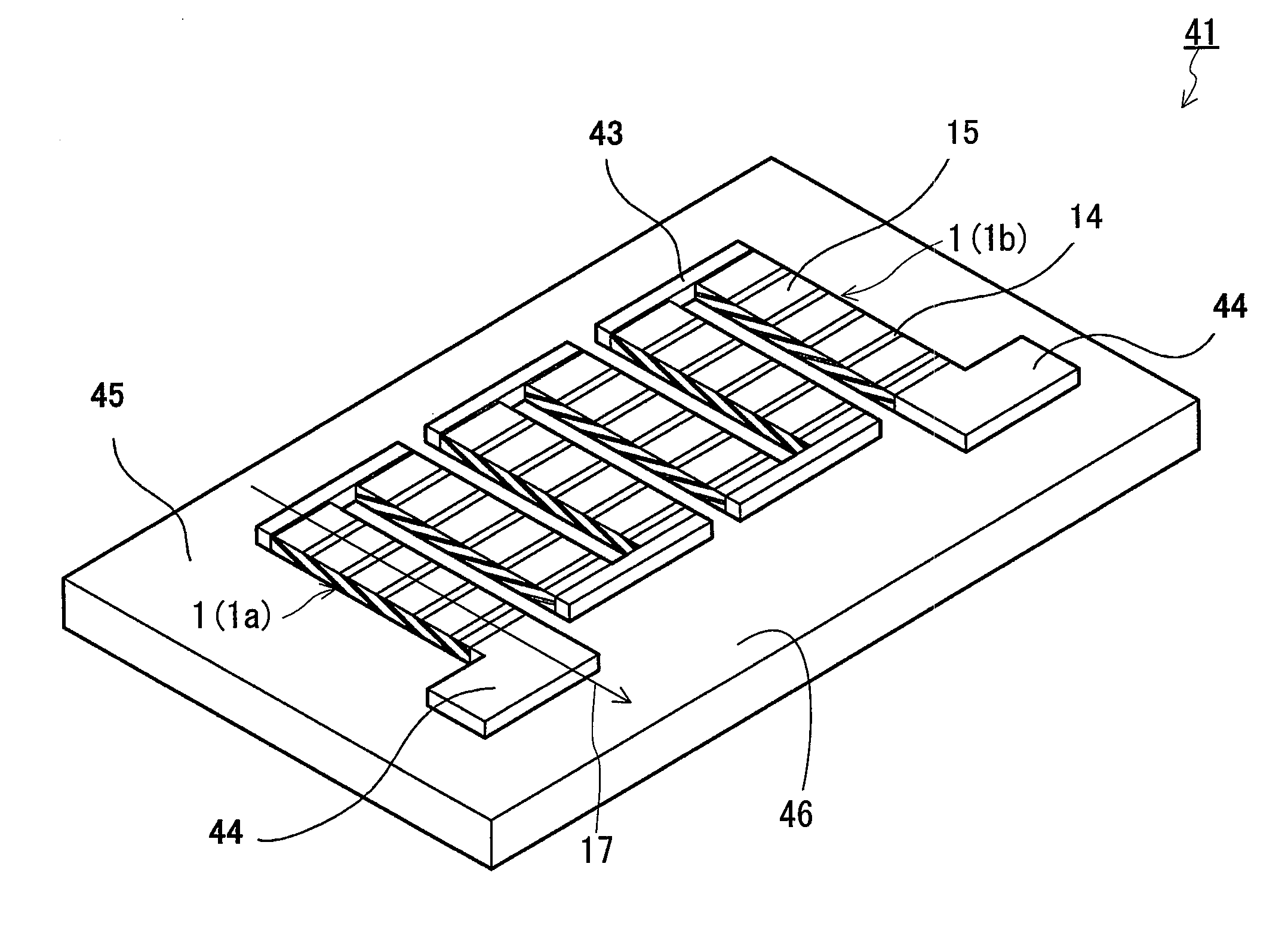
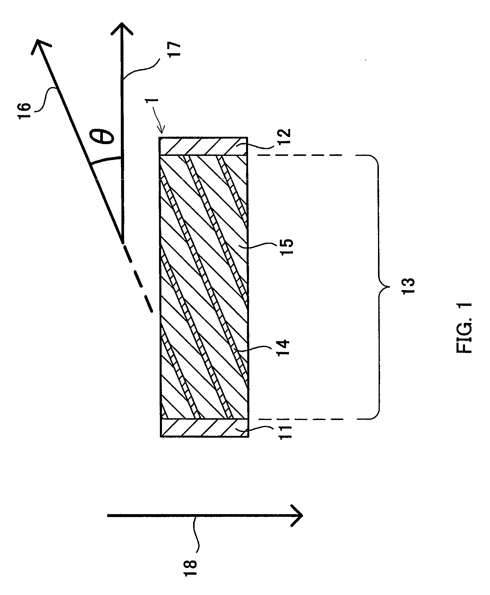
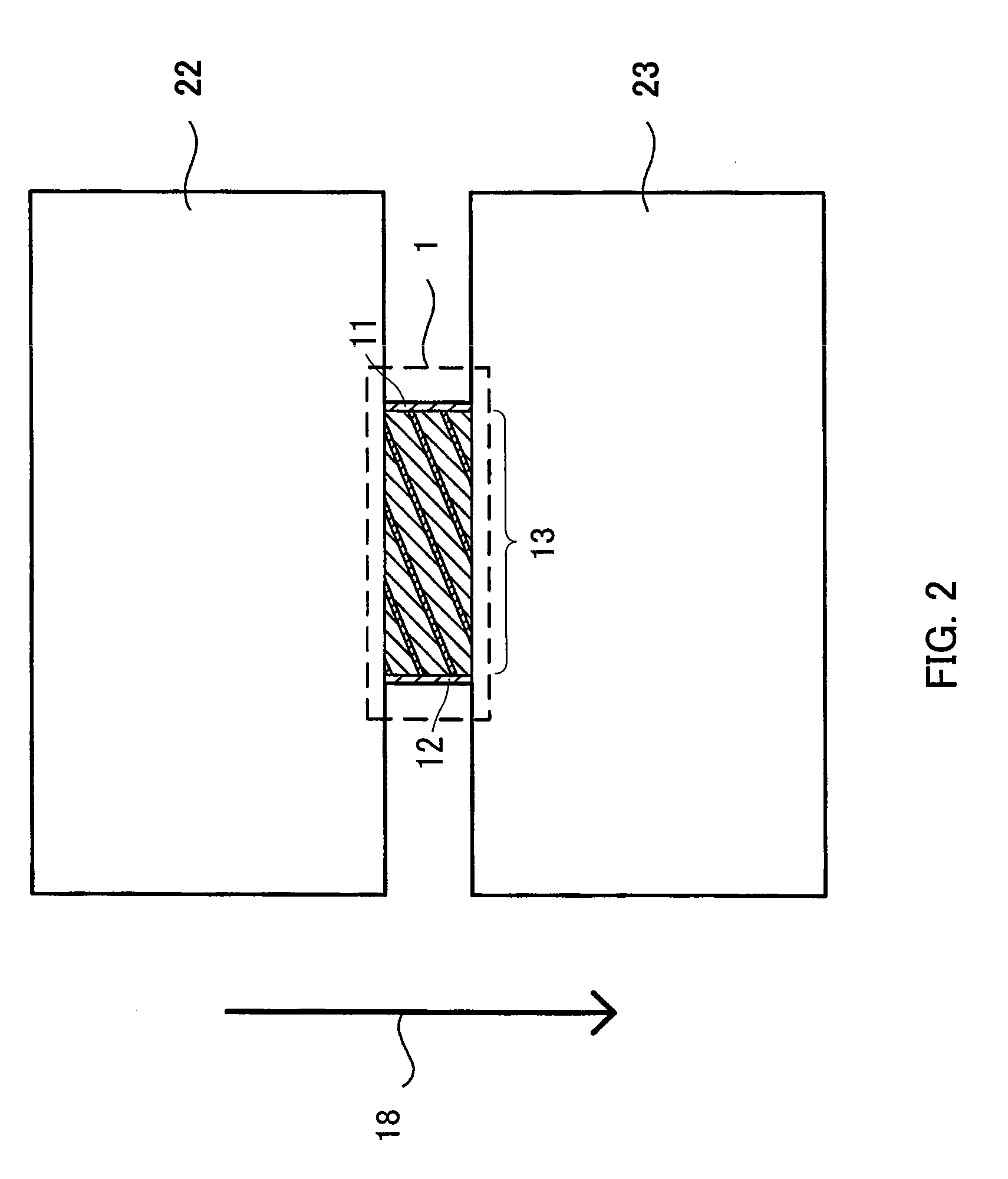
[0056]In Example 1, thermoelectric power generation elements 1 as shown in FIG. 1 were produced using SrB6 and several types of metals (Au, Ag, Cu and Al), and then the thermoelectric power generation characteristics thereof were evaluated.

[0057]First, a metal foil (Au foil, Ag foil, Cu foil, or Al foil) with a size of 100 mm×100 mm and a thickness of 20 μm was prepared, and a 2.0-μm thick SrB6 film was formed on each surface of the metal foil by the sputtering method.

[0058]Next, a sheet of a SrB6 film / a metal foil / a SrB6 film formed as described above was cut into a size of 50 mm×50 mm to form small strip pieces. Two hundred small pieces thus formed were superimposed together and were subjected to heat pressure bonding at 250° C. for one hour under a reduced pressure of 10−4Pa while a load of 100 kg / cm2 was applied in the direction in which they were laminated. Thereafter, it was subjected to cutting and polishing and thus a laminated original plate with a size of 3 mm×48 mm and ...

example 2

[0064]In Example 2, Ag or Cu was used as the metal for forming a metal layer and elements with different thickness ratios between the metal layer and the SrB6 layer from one another were produced in the same manner as in Example 1. While the inclination angle θ was fixed at 30°, the thickness of the metal foil used for forming the element was changed to 40 μm, 50 μm, 60 μm, 70 μm, 80 μm, 90 μm, 95 μm, 98 μm, and 99 μm, and the elements were formed so that the lamination cycle of the metal layer and the SrB6 layer was 100 μm. The thickness ratios of the SrB6 layers to the laminates of the elements thus formed were 60%, 50%, 40%, 30%, 20%, 10%, 5%, 2%, and 1%, respectively.

[0065]With respect to the elements thus produced, the power factors thereof were evaluated in the same manner as in Example 1. The results thereof are indicated in Table 2.

TABLE 2[Change in power factor (μW / (cm · K2)) of elements accordingto thickness ratio of SrB6 layer to laminate]Thickness ratio of SrB6layer to l...

example 3

[0067]In Example 3, while Cu was used as the metal for forming the metal layers, and elements that were different in the thickness ratio between the metal layer and the SrB6 layer and inclination angle θ from one another were produced in the same manner as in Example 1. The inclination angle θ was changed at 50 intervals from 10° to 50°, the thickness of each Cu foil used for forming the elements was fixed at 20 μm, the thickness of the SrB6 film formed on the surface of the Cu foil was changed to 0.25 μm, 0.5 μm, 1 μm, 2 μm, 4 μm, and 8 μm. Thus elements were formed.

[0068]With respect to the elements thus produced, the power factors thereof were evaluated in the same manner as in Example 1. The results are shown in Table 3 below.

TABLE 3[Change in power factor (μW / (cm · K2)) of element in termsof inclination angle θ and thickness ratio of SrB6 layer to laminate:metal forming metal layer (thickness of 20 μm) was Cu]Inclination angle θ101520253035404550Thickness of SrB68 (μm) / 23303232...


PUM


Abstract

The present invention provides an electric power generation method using a thermoelectric power generation element, a thermoelectric power generation element, and a thermoelectric power generation device, each of which has high thermoelectric power generation performance and can be used for more applications. The thermoelectric power generation element includes a first electrode and a second electrode that are disposed to oppose each other, and a laminate that is interposed between the first and second electrodes and that is electrically connected to both the first and second electrodes, where the laminate has a structure in which SrB6 layers and metal layers containing Cu, Ag, Au, or Al are laminated alternately, a thickness ratio between the metal layer and the SrB6 layer is in a range of metal layer: SrB6 layer=20:1 to 2.5:1, lamination surfaces of the SrB6 layers and the metal layers are inclined at an inclination angle θ of 20° to 50° with respect to a direction in which the first electrode and the second electrode oppose each other, and a temperature difference applied in a direction perpendicular to the direction in the element generates a potential difference between the first and second electrodes. The electric power generation method and thermoelectric power generation device each use the element.

Description

BACKGROUND OF THE INVENTION[0001]1. Field of the Invention[0002]The present invention relates to an electric power generation method using a thermoelectric power generation element, which is a method of obtaining electrical energy directly from thermal energy. Furthermore, the present invention also relates to a thermoelectric power generation element that converts thermal energy directly into electrical energy and the method of producing the same, as well as a thermoelectric power generation device.[0003]2. Description of the Related Art[0004]Thermoelectric power generation is a technique for converting thermal energy directly into electrical energy by utilizing the Seebeck effect whereby an electromotive force is generated in proportion to the temperature difference applied to both ends of a material. This technique is used practically in, for example, remote area power supply, space power supply, and military power supply.[0005]A conventional thermoelectric power generation eleme...

Claims


Application Information

Patent Timeline
IPC IPC(8): H01L35/14H01L37/00H01L35/34
CPCH01L35/22H02N11/002H01L35/34H01L35/32H10N10/855H10N10/01H10N10/17
Inventor ZENITANI, YUJIKANNO, TSUTOMUADACHI, HIDEAKIYAMADA, YUKA
Owner PANASONIC CORP
Why Eureka
Try Eureka