
Method for adjustment of a b1 field of a magnetic resonance apparatus

Inactive Publication Date: 2008-09-25
SIEMENS HEALTHCARE GMBH
View PDF8 Cites 15 Cited by
  • Summary
  • Abstract
  • Description
  • Claims
  • Application Information

AI Technical Summary

Benefits of technology

[0016]An object of the present invention is to provide tools with which the homogeneity of the B1 field can be adjusted in a beneficial manner for an examination with a magnetic resonance apparatus.
[0021]An improved estimation of a SAR value to be expected, as well as the electrical field and the power distribution in the human body, advantageously enabled. The ratio of a local SAR value to a global SAR value can be further optimized in order to prevent an excessive increase of the local SAR value.

Problems solved by technology

Problems occur in the adjustment of the homogeneity of the B1 field due to the use of increasingly strong magnetic field strengths in magnetic resonance tomography systems and the increasing excitation frequencies associated with the use of such strong fields.
Inhomogeneous image brightnesses dependent on the patient cannot be reduced or avoided by a uniformly designed radio-frequency coil.
A direct determination of the electrical field is not possible, but it can be analyzed with the use of complicated simulation programs and simulation calculations.

Method used


Image

  • Method for adjustment of a b1 field of a magnetic resonance apparatus
  • Method for adjustment of a b1 field of a magnetic resonance apparatus
  • Method for adjustment of a b1 field of a magnetic resonance apparatus

Examples


Embodiment Construction

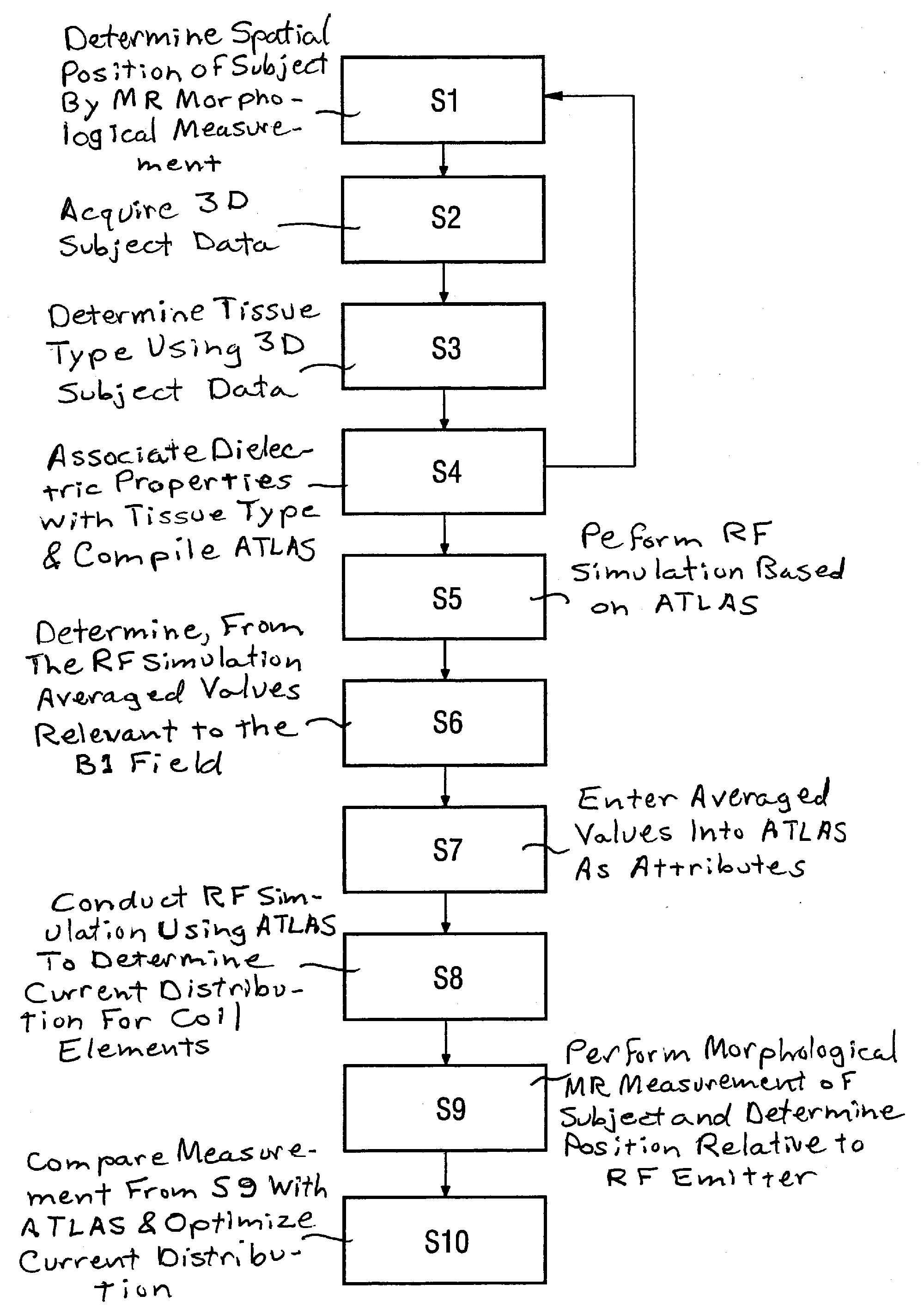
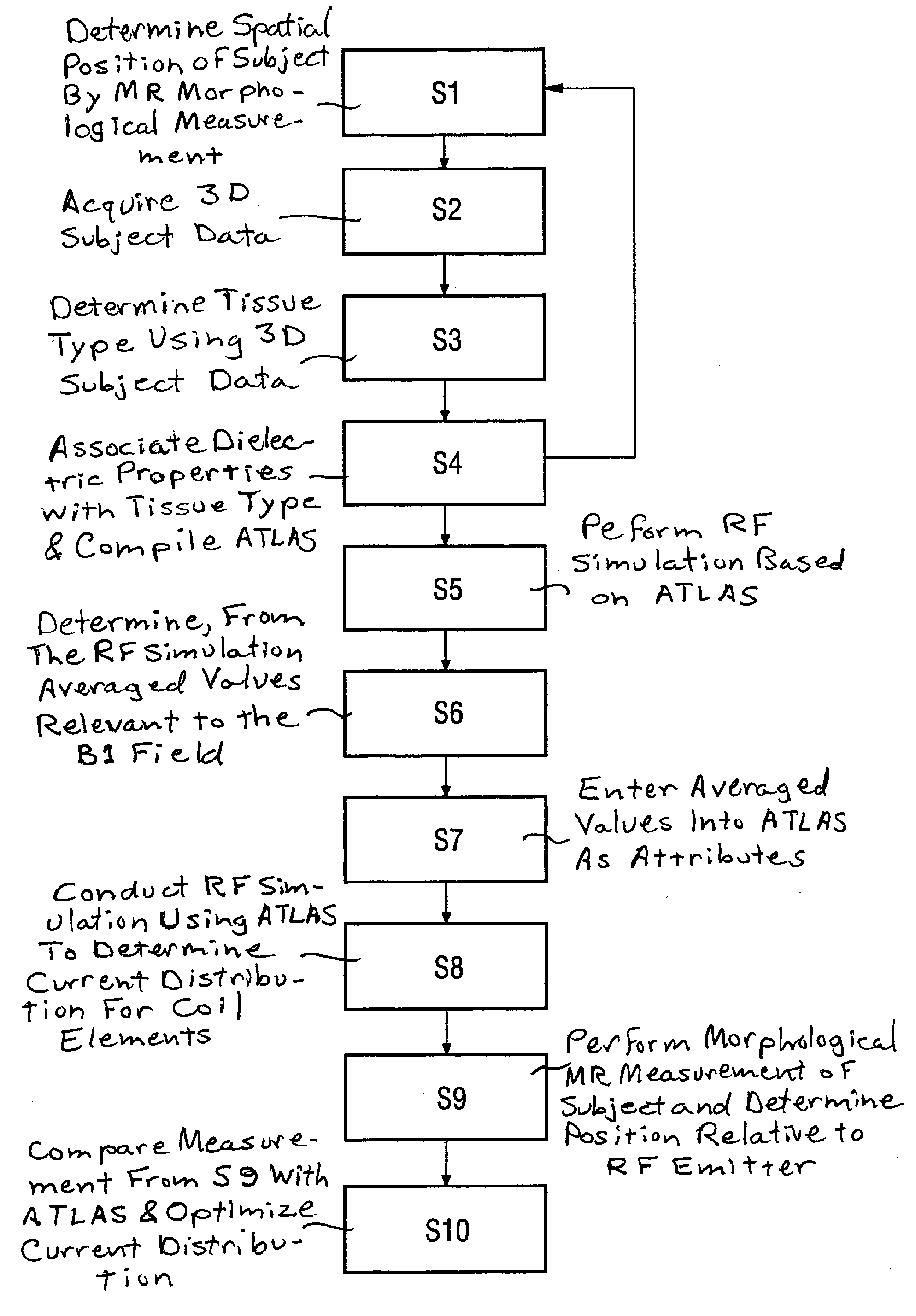
[0023]The invention is explained in an exemplary and non-limiting manner using the head of a subject to be examined as the examination subject.

[0024]In a first step S1 a spatial position is determined by conducting a morphological magnetic resonance measurement of a head.

[0025]The relative position of the head describes not only its alignment relative to reference axes but also the distance therefrom to a transmission antenna (an RF coil) or to the coil elements thereof. The transmission antenna is used in the morphological magnetic resonance measurement.

[0026]The position of the head is established and registered in relation to a coordinate system predetermined by the atlas.

[0027]In a second step S2, morphological samples (“scans”) of the head are conducted in order to acquire three-dimensional associable measurement subject data, namely head data.

[0028]Sequences designated as “MPRAGE” sequences (“Magnetization Prepared Rapid Gradient Echo Imaging”, MPRAGE) are preferably used that...


PUM


Abstract

In a method for adjustment of a B1 field in a magnetic resonance apparatus, the position of the measurement subject relative to a coordinate system is determined from a plurality of measurement subjects with a morphological magnetic resonance measurement. Three-dimensionally associable measurement subject data are determined from the measurement subject. Respective tissue types of the measurement subject are determined using the three-dimensional measurement subject data and a segmentation of the measurement subject into regions is effected using the tissue types. Known dielectric properties are respectively associated with the tissue types. The segmentation and the association for all positions of the measurement subject are recorded in respective entries of a database, such that the database contains all entries of the measurement subjects. A radio-frequency simulation for an transmission coils is implemented with the entries of the database, with which electrical field distributions and / or B1 field distributions related to spatial elements are determined as a simulation result and are entered as results into the database. For further magnetic resonance examinations, the entries of the database are used for determination of an optimized current distribution for elements of a transmission coil with which the B1 field is ultimately adjusted.

Description

BACKGROUND OF THE INVENTION[0001]1. Field of the Invention[0002]The present invention concerns a method for adjustment of a B1 field in a magnetic resonance apparatus, and a method for generation of a database for this purpose.[0003]2. Description of the Prior Art[0004]In the operation of a magnetic resonance apparatus, the examination subject is exposed to radio-frequency (RF) energy, in the form of RF pulses. The RF energy causes the nuclear spins in the examination subject that have been previously aligned by a strong, static magnetic field, to be deflected from the aligned (equilibrium) orientation. The precessing nuclear spins, as they return to their equilibrium position, cause an RF signal to be emitted from the subject, which is detected and analyzed to generate an image of the subject. The electromagnetic field that is produced by the emitted RF energy is referred to as the B1 field.[0005]Problems occur in the adjustment of the homogeneity of the B1 field due to the use of ...

Claims


Application Information

Patent Timeline
IPC IPC(8): G01R33/48
CPCG01R33/288G01R33/36G01R33/583G01R33/5612G01R33/5659G01R33/5608
Inventor FONTIUS, JOERG ULRICHSCHMITT, FRANZWICKLOW, KARSTEN
Owner SIEMENS HEALTHCARE GMBH
Learn More