

Projection type zoom lens and projection type display apparatus
a projection type, zoom lens technology, applied in the direction of lenses, optics, instruments, etc., can solve the problems of not essentially solving the deviation of the point of focus, the difficulty of substantially correcting the lateral chromatic aberration, etc., to achieve the effect of effectively alleviating the chromatic aberration, and reducing the occurrence of comatic aberration
- Summary
- Abstract
- Description
- Claims
- Application Information
AI Technical Summary
Benefits of technology
Problems solved by technology
Method used
Image

Examples
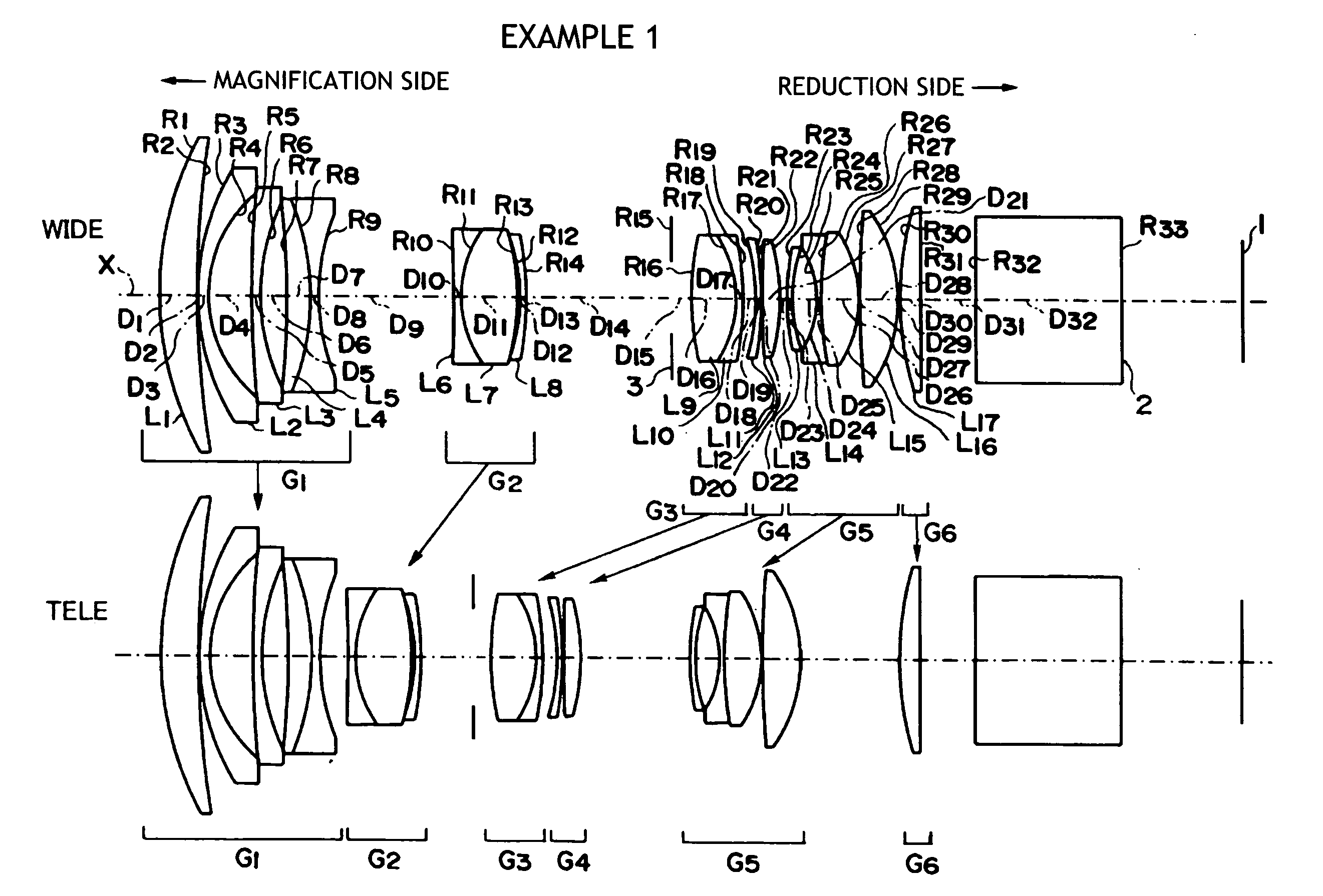
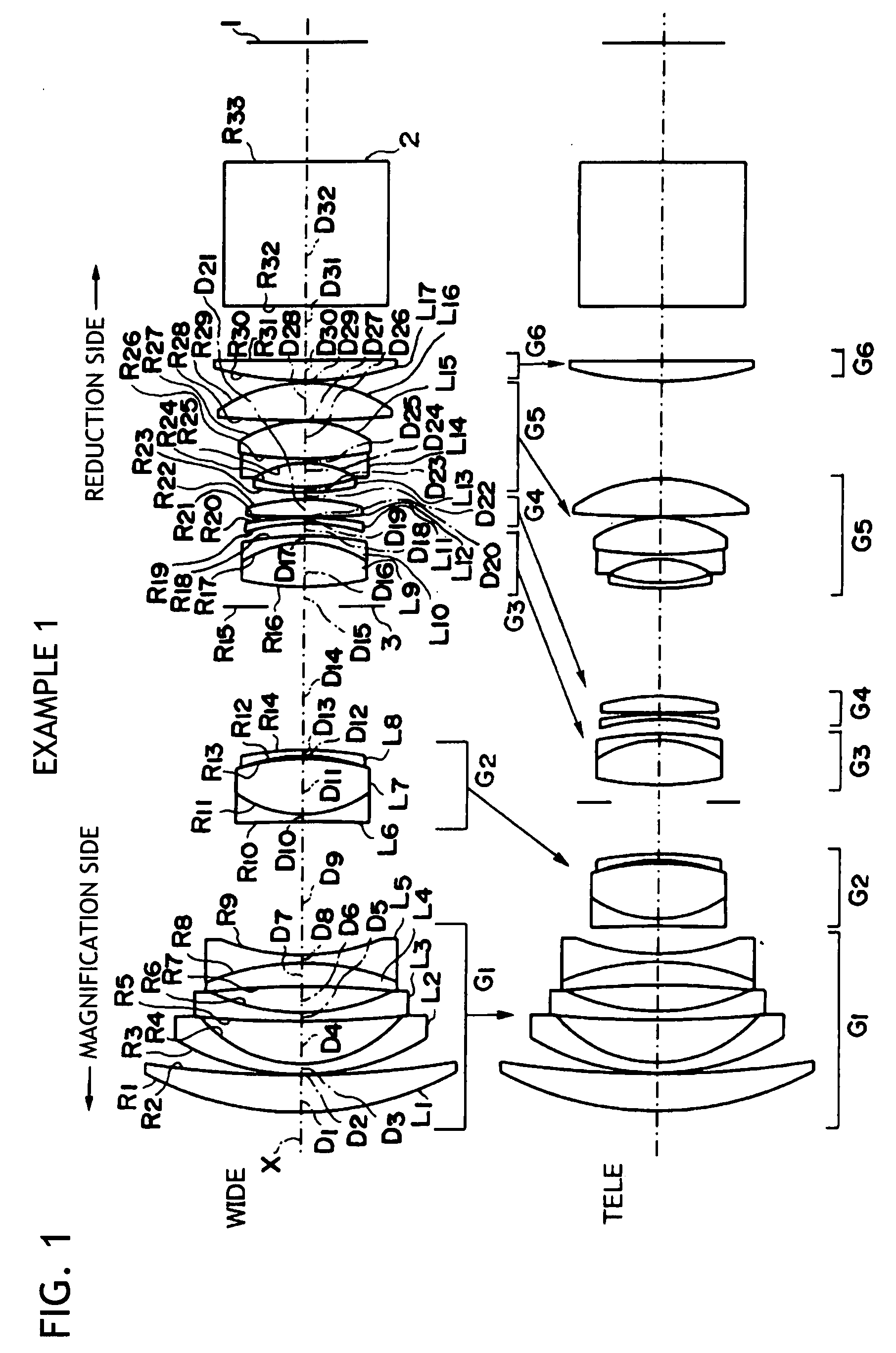
example 1
[0073]A schematic configuration of the projection type zoom lens according to Example 1 is shown in FIG. 1. This projection type zoom lens includes, in order from the magnification side, the first lens group G1 having a negative refractive power and the second to sixth lens group G2 to G6 having positive refractive power.
[0074]Since the description of the lens configuration of each group in Example 1 has been given in the description of the embodiment, a redundant description will be omitted. It is noted that the ninth lens L9 of the third lens group G3 is set as a positive lens made of the anomalous dispersion glass material having 70 or more in Abbe number.
[0075]Values of the radius of curvature R (unit: mm) of each lens surface of this projection type zoom lens, the central thickness of each lens and air spacing between the lenses (hereafter, these will be collectively referred to as an axial surface distance) D (unit: mm), and a refractive index N and the Abbe number at the d-li...
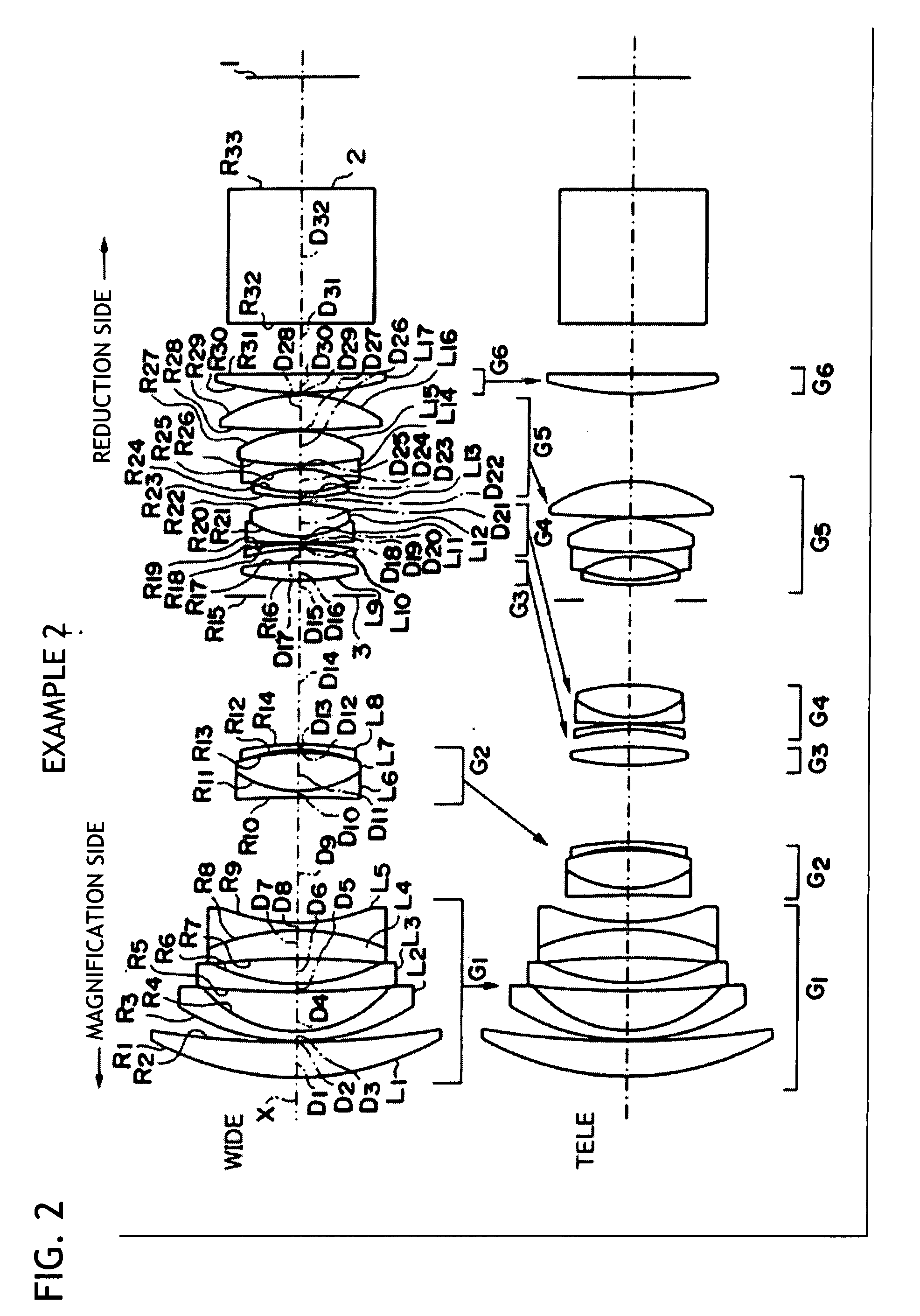
example 2
[0082]A schematic configuration of the projection type zoom lens according to Example 2 is shown in FIG. 2. In this Example, a description which is a duplicate of the description on Example 1 will be omitted.
[0083]The lens configuration of the projection type zoom lens according to Example 2 is substantially similar to that of Example 1, but differs mainly in the configurations of the third lens group G3 and the fourth lens group G4. Namely, the third lens group G3 is includes a single ninth lens L9 formed of a biconvex lens. In addition, the fourth lens group G4 includes, in order from the magnification side, the tenth lens L10 formed of a negative meniscus lens with the concave surface directed to the magnification side, the eleventh lens L11 formed of a negative meniscus lens with the concave surface directed to the reduction side, and the twelfth lens L12 formed of a biconvex lens. The eleventh lens L11 and the twelfth lens L12 are cemented to each other. In addition, the twelft...
example 3
[0091]A schematic configuration of the projection type zoom lens according to Example 3 is shown in FIG. 3. In this Example, description which is a duplicate of the description on Example 2 will be omitted.
[0092]The lens configuration of the projection type zoom lens according to Example 3 is substantially similar to that of Example 2, but differs mainly in the configurations of the fourth lens group G4 and the fifth lens group G5. Namely, the fourth lens group G4 differs from that of Example 2 in that the fourth lens group G4 includes, in order from the magnification side, the tenth lens L10 formed of a negative meniscus lens with the concave surface directed to the magnification side and the eleventh lens L11 formed a biconvex lens. In addition, the construction differs from that of Example 2 in that the positive lens made of the anomalous dispersion glass material having 70 or more in Abbe number is set as the fourteenth lens L14 of the fifth lens group G5. In this Example, since...
PUM
 Abstract
Description
Claims
Application Information