Variable Lens System

a lens system and variable technology, applied in the field of optical lens systems, can solve the problems of limited magnification of known electrowetting lenses, limited field flattening and aberration reduction possibilities, and the module is only suitable for low-resolution cameras, so as to reduce building height, reduce building height, and long focal range

Inactive Publication Date: 2008-09-25
KONINKLIJKE PHILIPS ELECTRONICS NV
View PDF7 Cites 39 Cited by
  • Summary
  • Abstract
  • Description
  • Claims
  • Application Information

AI Technical Summary

Benefits of technology

[0022]The position of the electrowetting lens in the first lens group may result in a small diameter electrowetting lens, resulting also in a low building height and a long focal range. The building height can be further reduced when, in the situation that no voltage is applied, the radius of the curvature of the meniscus is having the same sign as the radius of the curvature of the lens surface in contact with the fluid. A low building height is suitable for e.g. camera application, in mobile telephones.
[0023]The stop should preferably be placed close behind or integrated and close to the exit window of the electrowetting lens, when using a small electrowetting lens in the first lens group. This stop can block unwanted reflections in the first lens group, which reflections may otherwise reach the image sensor and result in ghost images.

Problems solved by technology

The known electrowetting lens has limited magnification, field flattening and aberration reduction possibilities due to the limited number of optical surfaces.
As a result, the module is only suitable for low-resolution cameras such as CIF and VGA.
For cameras with for higher resolution sensors such as the 500k-pixel range (S)VGA image sensors, the 1M-pixel range XGA image sensors and mega-pixel devices this is not sufficient.
Due to this location straylight entering the lens system can still reflect from the cylindrical wall of the lens system towards the image sensor, resulting in ghosting.
As a result, in such a design the amount of space available for the lens stack is not being used economically, unnecessarily limiting the performance of the module.
The above disclosures do only describe single aspects, such as focusing or zooming, of the applied electrowetting lenses, which are not sufficient for compact high-resolution imaging systems as applied in e.g. mobile camera modules.
None of the above disclosures addresses the problem of achromatisation, which is needed to achieve a good optical colour correction of the imaging lens system.
Both the above mentioned methods for providing an achromatic lens system are not applicable for electrowetting lenses, because in electrowetting lenses the optical power changes with the radius of the meniscus between the two fluid depending on the applied voltage, while the above mentioned methods apply to fixed optical power lenses only.

Method used


Image

  • Variable Lens System
  • Variable Lens System
  • Variable Lens System

Examples


first embodiment

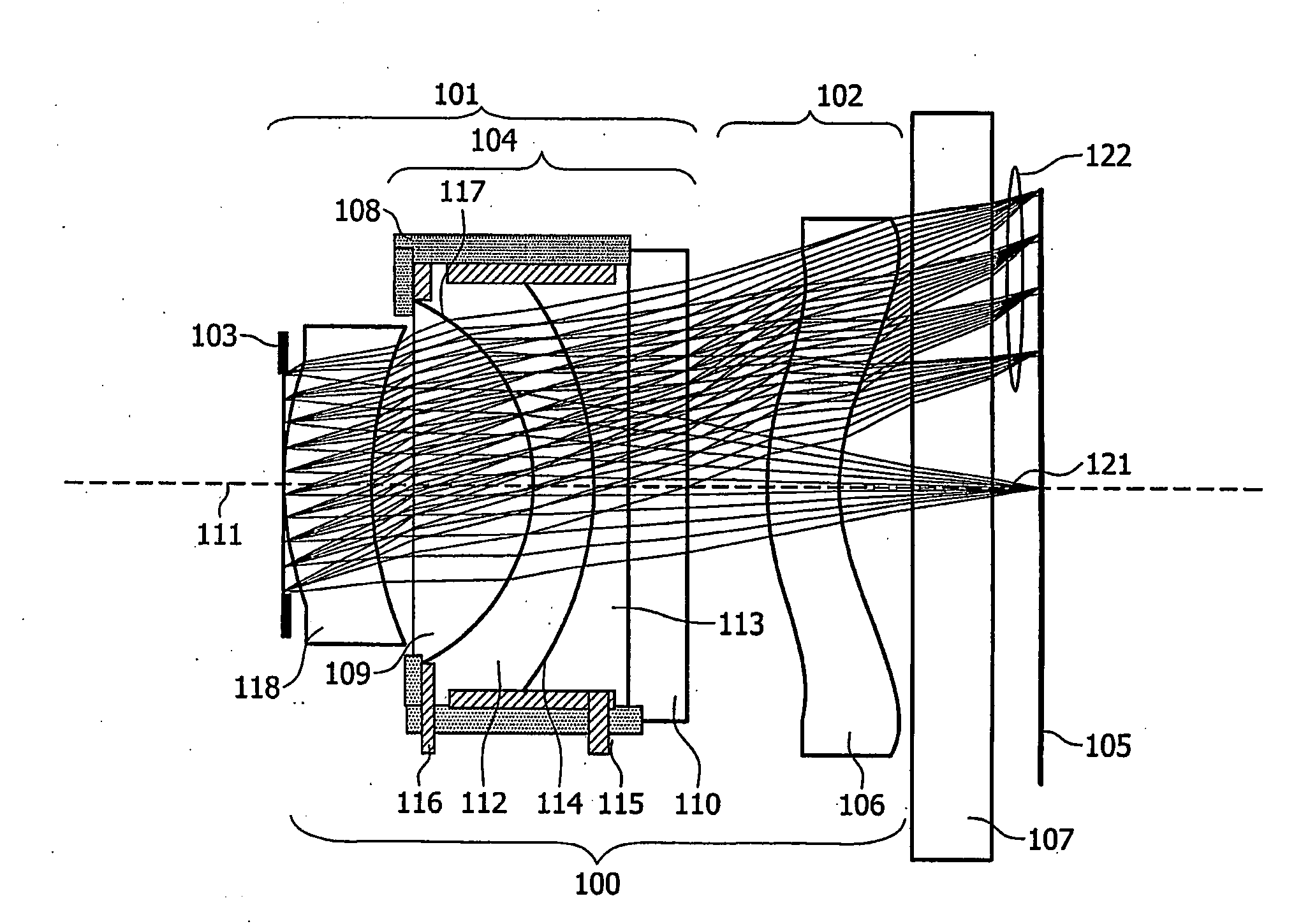
[0037]FIG. 1 schematically shows an optical lens system in accordance with the present invention. The optical lens system (100) comprises two lens groups 101 and 102 and a stop 103 located in front of the first lens group. The first lens group 101 comprises an electrowetting lens 104 as variable lens and acts as a variable focus lens. In the example shown in FIG. 1 the first lens group also determines the magnification of the optical lens system to match the size of the images to the size of the image sensor 105 located behind the optical lens system. The second lens group 102 comprises a field-flattening lens 106 that flattens the focal plane for light rays 122 entering from a field angle in the object space. The image sensor 105 is covered with a transparent cover 107, here a plan parallel plate.

[0038]The electrowetting lens includes a chamber 108 having an entrance window 109 and an exit window 110, and an optical axis 111 extending longitudinally through the chamber. The chamber...

second embodiment

[0048]In the invention, the electrowetting lens can be made substantially achromatic by a proper choice of the materials of the contacting fluid 112 and the entrance window 109 in combination with an optimised surface curvature for the fluid-window interface 109. This choice of materials may be done on parameters such as refractive index and Abbe-number.

[0049]In order to be able to have sufficient freedom in choosing the appropriate lens materials and fluids it is required to allow of a wide range of refractive indices. This can result for example in a substantial difference in refractive index of the material used for the window and the contacting fluid. Allowing such a substantial difference in refractive indices also requires a substantial difference in Abbe-numbers for the window and fluid to optimise for a substantially achromatised electrowetting lens. The choice of materials for window, fluid and curvature also may be optimised for substantially achromatising the total optica...

third embodiment

[0053]FIG. 4 shows schematically an optical lens system according to the invention is schematically shown. In this embodiment a combination of choices of fluids and window materials (choices for e.g. refractive index and Abbe-number) with choices of the curvature of both the surfaces of the entrance and exit window is used to substantially reduce the aberrations introduced by the electrowetting lens or even total optical lens system. The optical lens system 200 comprises two lens groups 201 and 202 and a stop 203 located between the first and second lens group. The first lens group 201 comprises an electrowetting lens 204 as variable lens and acts as a variable focus lens. The second lens group 202 determines the optical magnification using a lens 220 to match size of the images with the size of the image sensor 205 located behind the optical lens system. Also it reduces the chief-ray angle by means of a field-flattening lens 206. The image sensor 205 is covered with a transparent c...


PUM


Abstract

A compact and substantially achromatic optical lens system (100, 200) comprising an electrowetting lens (104, 204) is provided. The optical lens system is using an electrowetting lens in which at least one of the entrance window surface (117, 217) or exit window surfaces (219), being in contact with one of the fluids (112, 212, 113, 213), has a curvature. When the sign of the curvature of that surface has the same sign as the curvature of the meniscus when no voltage is applied, a low building height is achieved. The optical element (104, 204) not only acts as a focussing or zooming device, but that it also acts as an aberration reduction element for the other elements in the optical lens system (100, 200).

Description

FIELD OF THE INVENTION[0001]The present invention relates to an optical lens system using a variable lens comprising a first fluid and a second fluid which are in contact over a meniscus, to an imaging system including such an optical lens system and to a method of designing such a variable lens system and optical imaging system.BACKGROUND OF THE INVENTITON[0002]A variable lens is a device in which one or more properties of the lens can be controllably adjusted, e.g. in which the focal length or the position of the lens can be altered. An optical lens system is used to image an object on to an image sensor. This optical lens system can comprise a variable lens[0003]The general trend in the development of image sensors for camera modules is that they constantly increase in resolution. Starting from the low-resolution sensors such as the 100k-pixels range CIF image sensors and 300k-pixels image sensors, there are presently high-resolution mega-pixel image sensors available. These high...

Claims


Application Information

Patent Timeline
Patent Type & Authority Applications(United States)
IPC IPC(8): G02B3/14G02B7/02G02B13/00G02B26/02
CPCG02B3/14G02B7/028H04N5/2254G02B13/009G02B26/005G02B13/0075G02B7/02G02B7/04G03B30/00G02B2207/115
Inventor HENDRIKS, BERNARDUS HENDRIKUS WILHELMUSKUIPER, STEIN
Owner KONINKLIJKE PHILIPS ELECTRONICS NV
Why Eureka
Try Eureka