Assembled Magnetic Energy Generator as Well as Its Magnetic Light

Inactive Publication Date: 2008-09-25
LI JIN
View PDF4 Cites 0 Cited by
  • Summary
  • Abstract
  • Description
  • Claims
  • Application Information

AI Technical Summary

Benefits of technology

[0007]Accordingly, to achieve above object, the present invention provides a magnetic generator, comprising a pair of detachable magnetic bodies coupled with each other at a face to face manner to complete a magnetic circuit, wherein a fixed magnetic air gap is formed therebetween for accurately positioning a magnetic field center of the magnetic circuit, and for ensuring an electromagnetic induction current volume.
[0008]According to the present invention, the magnetic body further comprises a bakelite frame for enwinding electromagnetic induction coil. It is noted that the fixed magnetic air gap is capable of ensuring the electromagnetic induction current, therefore, the manageability and the reliability of the electromagnetic circuit could be enormously improved. Ultimately, the compatibility and quality of the product could be under control of the manufacturer so as to pave the way for industry-scale production.
[0009]It is noted that the magnetic body of the present invention has two separated magnetic members detachably coupled with each other at a face to face manner, wherein each of the magnetic member has at least two indented grooves defined on a facing side, such that when two magnetic member approach with each other, indented grooves respectively defined onto two magnetic members will correspondingly align to form at least two magnetic gaps interposed between two magnetic members. There are two engaging shoulder respectively defined at two side ends of the magnetic member for ensuring two magnetic members detachably coupled together to form the magnetic body. It is noted such engaging shoulders could ensure two engaging members attached at a stable manner. Finally, the insulated bakelites are correspondingly provided within the magnetic gaps for supporting the electromagnetic coils.
[0012]Or otherwise, the magnetic body of the present invention has two separated magnetic members detachably coupled with each other at a face to face manner, wherein each of the magnetic member has at least one indented groove defined on a facing side, such that when two magnetic member approach with each other, indented grooves respectively defined onto two magnetic members will correspondingly align to form at one magnetic gap interposed between two magnetic members. There are two engaging shoulders respectively defined at two side ends of the magnetic member for ensuring two magnetic members detachably coupled with each other to form the magnetic body. It is noted such engaging shoulder could ensure two engaging members attached at a stable manner. Finally, the insulated bakelites are correspondingly provided within the magnetic gaps for supporting the electromagnetic coils.

Problems solved by technology

And more importantly, the life-span of the light could be extended 16 times, the energy-saving efficiency could be increased around 35-45%, and the input efficiency could achieve 6 W-1500 W. however, the electrodeless lamp and the electromagnetic light introduced into the market had been complained about the inefficient structure and expensive costs.
The embodied electromagnetic light could not achieve the prospective efficiency claimed by the magnetic light.
That is to say, the magnetic light is still lingered within the initiating phrase after 15 years efforts, and is still far from wide development and spread in the market.
The high frequency electromagnetic induction device has been widely considered as a bottleneck of an efficient electromagnetic lamp.
As a result, the electromagnetic equivalent could not be managed in applications.
As a result, the electromagnetic intensity of the closed circuit could not be measured.
Furthermore, the separated magnetic body have been disposed with an unstable condition, wherein the distance, relative position, gap, space and air-gap between each other could not be secured, thus resulting the magnetic ring working in a constantly unstable status.
What is more, the soft magnetic ferrite of the electromagnetic induction device could not be relatively secured at a fixed position, after the circuit is charged to enable the induction magnetic filed to shine up the light, the high temperature emitted from the lamp and the soft magnet ferrite would affect the magnetic material thus generating expanding of the materials, as a result, the magnetic filed intensity could be not controlled.
The magnetic filed voltage could not controlled as well, the constantly soared magnetic current would result to the instability of the physical property of the magnetic materials provided onto the magnetic coil.
Furthermore, the magnetic air-gap would be continuously enlarged thanks to the unstable magnetic field intensity and the high temperature of the lamp, thus forming an uncontrollable cycle, i.e. the current and voltage would be increased as well.

Method used


Image

  • Assembled Magnetic Energy Generator as Well as Its Magnetic Light
  • Assembled Magnetic Energy Generator as Well as Its Magnetic Light
  • Assembled Magnetic Energy Generator as Well as Its Magnetic Light

Examples


Embodiment Construction

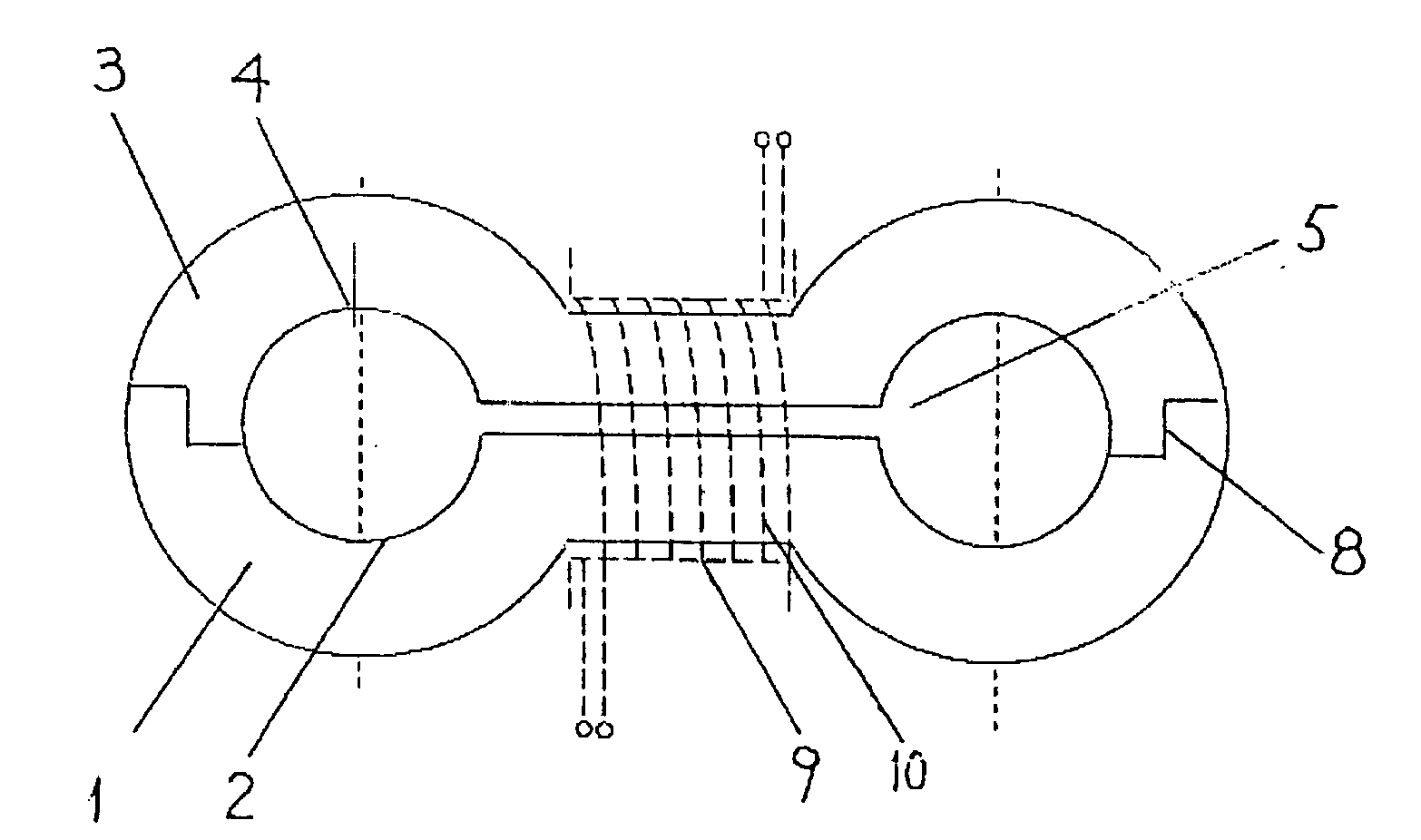
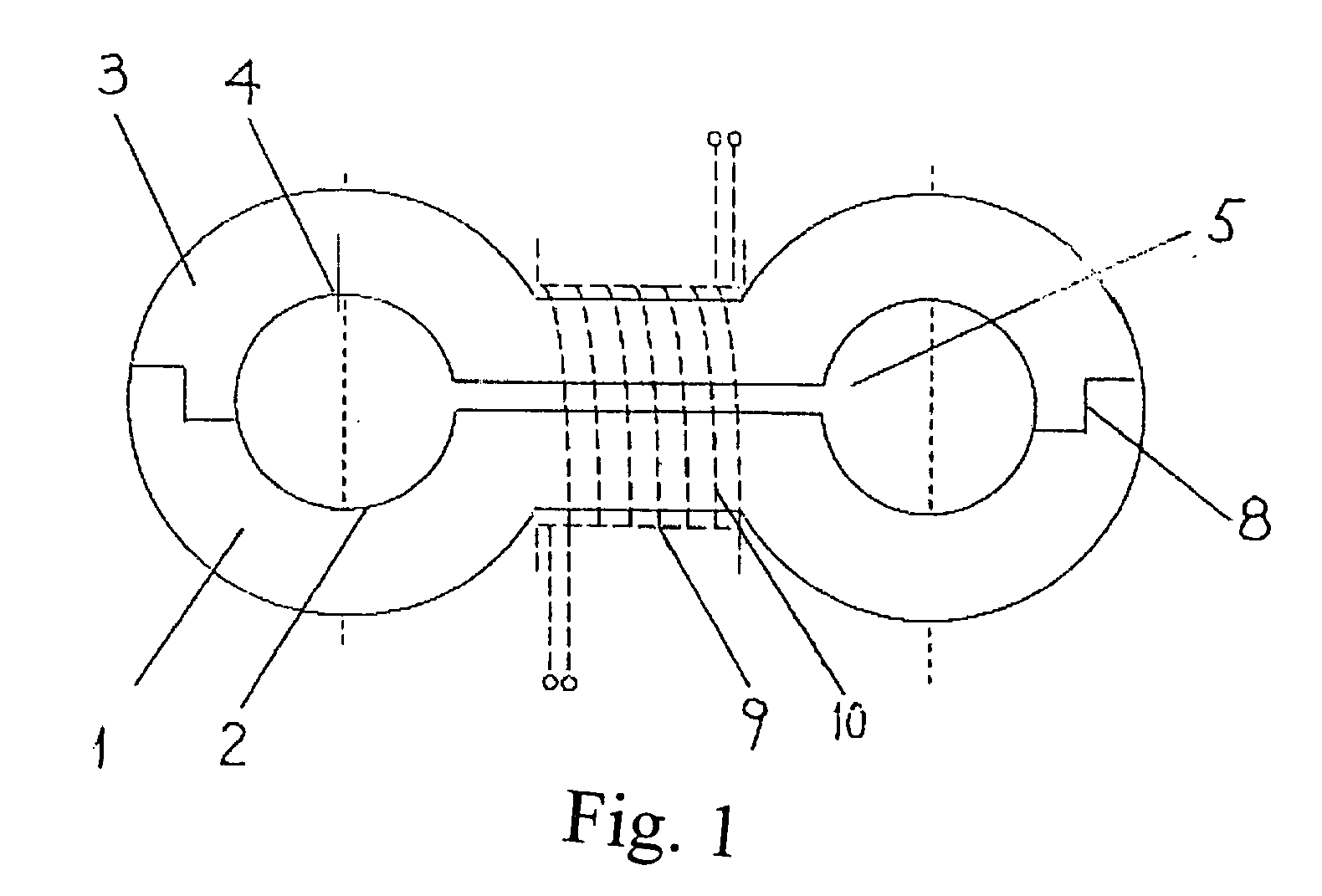
[0028]Referring to FIG. 1, the magnetic energy generator according to the present invention is illustrated, wherein the magnetic energy generator 1 is an assembled magnetic body comprising a pair of detachable magnetic members, namely magnetic member 1 and magnetic member 3, jointed with each other at a face to face manner. The magnetic member 1 has two indented grooves 2 at a facing side, and the magnetic 2 has two indented grooves 4 at a correspondingly facing side as well, wherein two side ends of the respective magnetic member are adapted to be coupled with counterpart side end of the opposite magnetic member so as to joint two separated magnetic members together in such a manner that when two detachable magnetic members approach with each other, two correspondingly mated indented grooves will be aligned and combined, and a magnetic air gap 5 will be formed between two indented grooves. It is noted such magnetic air gap 5 is defined between two detachable magnetic members as wel...


PUM


Abstract

A wrapper type combined magnetic energy generator and a magnetic energy lamp of the present invention belong to the field of illumination. Especially, it is a magnetic energy generator used in the magnetic energy lamp that can produce the electromagnetic energy to excite the illuminative devices. The magnets of the magnetic energy generator are two split type combined magnets. More than one flute is provided on one side of one magnet and the flutes of the two magnets correspond to each other. The fixed spaces are produced between the two flutes of the two magnets. The spaces are communicated with the two flutes to be located exactly. The lamp body of the magnetic energy lamp is provided and fixed on the magnetic energy generator. These two split type combined magnets of the magnetic energy generator wrap the hollow lamp body of the magnetic energy lamp, respectively. The structure of the present invention is simple. It can be made easily and its cost is low. So it provides a reliable technique implementation project for the large-scale industrialization.

Description

BACKGROUND OF THE PRESENT INVENTION[0001]1. Field of Invention[0002]The present invention relates to luminous means, and more particularly, relates to a kind of magnetic light utilizing an assembled magnetic generator for activating a luminous body to shine up the light.[0003]2. Description of Related Arts[0004]Magnetic lights utilize high-frequency magnetic energy resonance theory to replace conventional filament illumination theory, which employs LC series filaments having fluorescent electrode, wherein the electrode could be heated to activate fluorescent powder for illumination. By applying the magnetic lights, the luminous efficiency would be significantly improved as much as 20% and the fluorescent light-attenuating phenomena could be neglected. And more importantly, the life-span of the light could be extended 16 times, the energy-saving efficiency could be increased around 35-45%, and the input efficiency could achieve 6 W-1500 W. however, the electrodeless lamp and the elec...

Claims


Application Information

Patent Timeline
IPC IPC(8): G11B5/55
CPCH01J65/048
Inventor LI, JIN
Owner LI JIN
Why Eureka
Try Eureka