
Lightning Diverter for Conducting a Lightning-Induced Electrical Current and a Method of Producing the Same

a technology of diverter and electrical current, which is applied in the installation of lighting conductors, sustainable manufacturing/processing, protective material radiating elements, etc., can solve the problems of increased risk of being struck by lightning, and service and maintenance becoming rather expensive and complex, and achieving low weight and not prone to cracking

Active Publication Date: 2008-09-25
LM GLASSFIBER
View PDF4 Cites 9 Cited by
  • Summary
  • Abstract
  • Description
  • Claims
  • Application Information

AI Technical Summary

Benefits of technology

[0007]It is therefore an object of the present invention to present a segmented diverter strip with a longer life-time than existing models and with as low as possible lift-off capacity to be an effective lightning conductor, and yet on the same time being simple and easy to place even on curved surfaces. It is a further objective to describe a method of production of diverter strips, which is cost effective but also provides high accuracy as to the spacing of the segments and their adhesion to the layer underneath.

Problems solved by technology

The increasing development in the field of wind energy plants is reflected in large units with still higher towers and longer blades resulting in the increased risk of being struck by a lightning.
The blades are usually the longest part of the wind energy plant, and they therefore have an increased risk of being struck by a lightning.
Wind energy plants are placed in e.g. large numbers in the sea in the form of windmill farms, resulting in the fact that service and maintenance becomes rather expensive and complex due to weather conditions and difficult access conditions.
Salt from the air deposits on e.g. the blades, thus making these conductive, which again increases the risk of these being struck by a lightning.
The strings must be exchangeable after strokes of lightning due to the damage caused by the strong heating resulting from the lightning current, which not only means monitoring of the wind energy plant and standstill during change, but also big expenses.
There is furthermore the risk of the strings getting loose and consequently affecting the aerodynamic properties of the blade negatively.
The strings must otherwise be made of a heavy material, resulting in undesired extra weight on the blade.
One of the problems when designing long blades is to lower the weight, in that the weight in itself not only makes the blades even heavier, but also the hub, the nacelle and the tower.
Such a position provides a good protection, but at the same time it results in aerodynamic disturbance.
Furthermore, these strips have the disadvantages of not lasting very long, as the segments easily get ripped off the base into which they are incorporated, either by the lightning or by simple wear.
Therefore, these ribbons often need to be renewed when having been exposed to lightning.
However, in many applications this is very costly and impractical.
Diverter strips according to U.S. Pat. No. 4,506,311 are furthermore seen to have the problem that the lightning current can jump from underneath the segments to the next, which increases the risk of the current jumping into the structure, which should be protected by the diverter.
Another disadvantage is that the strips are difficult to fasten onto the surfaces without unwillingly stretching the strips or ribbons a little, thereby changing the distances between the segments accordingly.

Method used


Image

  • Lightning Diverter for Conducting a Lightning-Induced Electrical Current and a Method of Producing the Same
  • Lightning Diverter for Conducting a Lightning-Induced Electrical Current and a Method of Producing the Same
  • Lightning Diverter for Conducting a Lightning-Induced Electrical Current and a Method of Producing the Same

Examples


Embodiment Construction

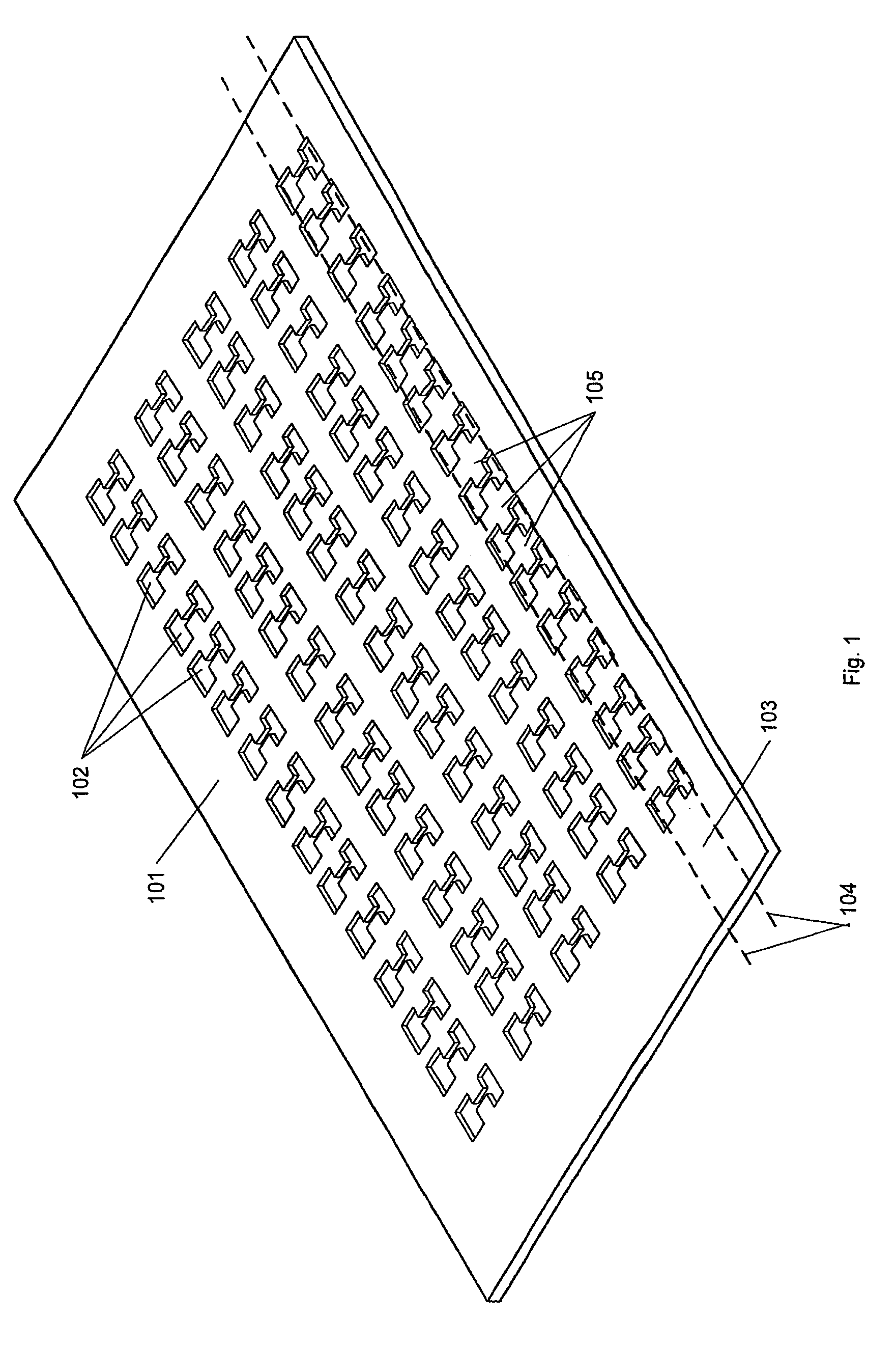
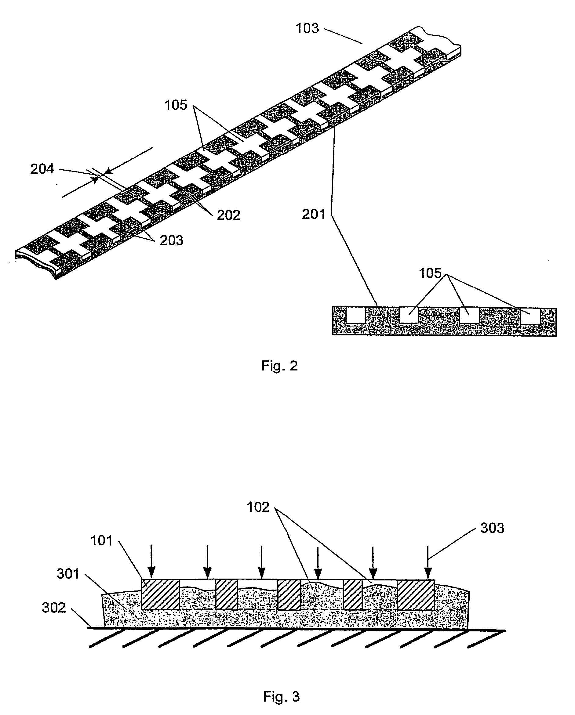
[0035]FIG. 1 shows a plate 101 used in the production of a lightning diverter as described in the following. The plate 101 is made of a material with good electrically conducting properties, preferably a metal such as stainless steel, copper, brass or the like. A number of holes 102 is cut into the plate 101 e.g. by laser cutting or punching. The holes 102 are applied in a pattern designed so that the plate can be divided into one or more strips 103 as shown by the hatched lines 104 in the figures where the strip will then consist of a number of segments 105 all spaced apart and not connected. The strip 103 does not necessarily have to be straight, but can be in any desired curved shape suitable for its purpose. In the embodiment of the plate as shown in FIG. 1 the resulting diverter will be a strip with a number of cross-shaped segments. Different patterns are shown in FIGS. 9 and 10.

[0036]Before the plate 101 is divided, the holes are filled with an electrically non-conductive mat...


PUM

PropertyMeasurementUnit
sizesaaaaaaaaaa
sizesaaaaaaaaaa
electrically conductiveaaaaaaaaaa

Abstract

The present invention concerns a method of producing a lightning diverter for conducting a lightning-induced electrical current, which is to be placed on structures such as wings on wind turbines, aircraft components, radomes and the like with the purpose of lightning protection. The method comprises the steps of making a plurality of holes in a plate of an electrically conductive material, filling said holes at least partly with one or more electrically non-conductive materials, and then finally dividing the plate—preferably into strips. The lightning diverter obtained hereby consists of a layer of electrically non-conductive material with a plurality of isolated segments of electrically conductive material.The invention further relates to a diverter strip with isolated segments of concave shapes being advantageous because of the good connection between the segments and the non-conductive material.

Description

[0001]The present invention relates to a method of producing a lightning diverter for conducting a lightning-induced electrical current and to be placed on structures such as wings on wind turbines, aircraft components, radomes and the like with the purpose of lightning protection. The present invention further relates to the design of a lightning diverter strip.BACKGROUND OF THE INVENTION[0002]The increasing development in the field of wind energy plants is reflected in large units with still higher towers and longer blades resulting in the increased risk of being struck by a lightning. The plants are typically secured from lightning strokes, so that a possible lightning current is attracted and led to the ground in a controlled mariner in order not to damage the sensitive elements in the wind energy plant. One of the most popular methods for securing lightning is by installing one or more so-called lightning receptors, which are conductive elements, and which are placed e.g. on th...

Claims


Application Information

Patent Timeline
Patent Type & Authority Applications(United States)
IPC IPC(8): H02H3/22H02H1/04H05F3/00H02G13/00B64D45/02F03D11/00H01Q1/28H01Q1/40H01Q1/42H01Q1/50
CPCB64D45/02F03D11/0033H01Q1/287H01Q1/40H01Q1/50Y10T29/49993Y02E10/721Y02E10/722H02G13/80Y10T29/49117Y10T29/49336H02G13/00F03D80/30F03D1/0675Y02E10/72Y02P70/50
Inventor DAHL, MORTENLILLEHEDEN, LARS TILSTEDHANSEN, LARS BO
Owner LM GLASSFIBER
Learn More