

Translucent ceramic, method for producing the same, optical component, and optical device
a technology of transparent ceramics and optical components, applied in the field of transparent ceramics, can solve the problems of double refraction, low moisture resistance of plastics, and difficulty in downsizing optical components and optical devices using such materials, and achieve high linear transmittance, high refractive index, and high anomalous dispersion.
- Summary
- Abstract
- Description
- Claims
- Application Information
AI Technical Summary
Benefits of technology
Problems solved by technology
Method used
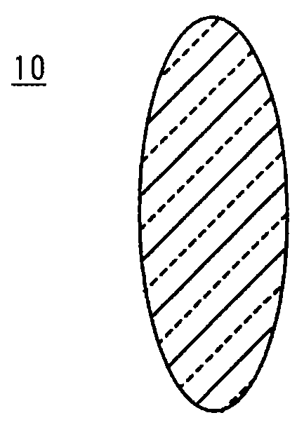
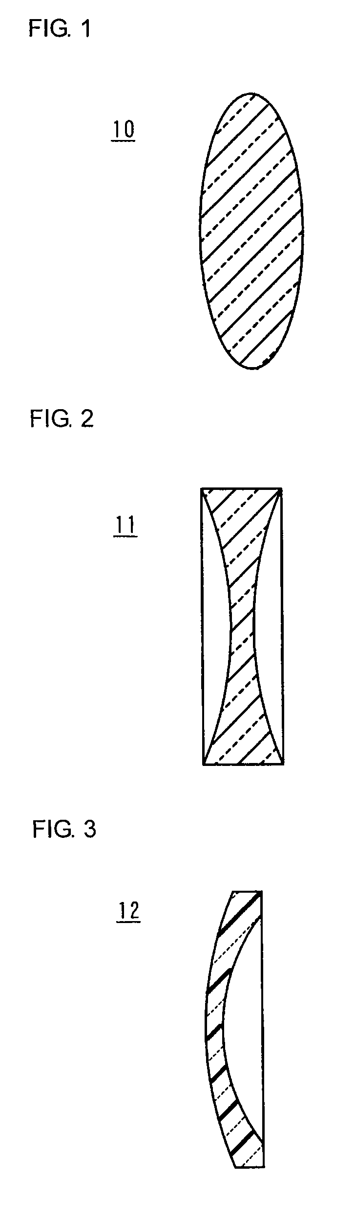
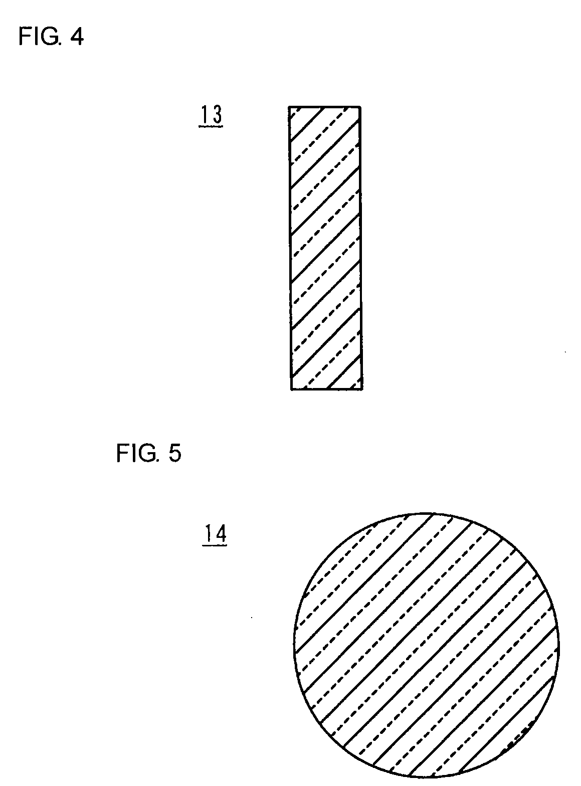
Image

Examples
experimental example 1
[0076]Highly pure powders of La (OH)3, Y2O3, Gd2O3, Yb2O3, Lu2O3, SnO2, ZrO2, TiO2, and HfO2 were prepared as raw materials. The raw materials were weighed out so as to prepare samples represented by the general formula AxByOw (w represents a positive number maintaining electroneutrality) shown in Table 1, and were then wet-mixed in a ball mill for 20 hours. The resulting mixtures were dried and then calcined at 1300° C. for 3 hours to prepare calcined powders. The w value after calcination was about 7.
[0077]In the column “B site element and content” in Table 1, the content is the same as the y value when the B site is constituted of a single element, and the sum of the contents represents the y value when the B site is constituted of two elements.
[0078]Then, the calcined powder and an organic binder were placed in a ball mill and wet-pulverized for 12 hours. The organic binder was ethyl cellulose. Binders, other than ethyl cellulose may be used as long as they function as a binder ...
experimental example 2
[0093]Sintered compacts having the same composition as Sample 6 prepared in Experimental Example 1 were produced at respective firing temperatures of 1625° C. and 1700° C. These samples were prepared under the same conditions as in the preparation of Sample 6 in Experimental Example 1, except for the firing temperature.
[0094]The samples prepared at different firing temperatures were evaluated for the linear transmittance, the refractive index, and the Abbe number in the same manner as in Experimental Example 1. The results are shown in Table 2. Table 2 also shows the evaluation results of Sample 6 prepared in Experimental Example 1 (at a firing temperature of 1675° C.).
TABLE 2LinearFiringtransmittance (%)RefractiveAbbetemperature633 nmIndex ndnumber νd1625° C.73.42.086632.41675° C.75.22.086632.41700° C.63.92.086632.4
[0095]As is clear from Table 2, the linear transmittances of the samples fired at 1625° C. or 1700° C. are slightly inferior to the sample fired at 1675° C. but were as ...
experimental example 3
[0096]A sintered compact having the same composition as Sample 6 prepared in Experimental Example 1 was produced under the same conditions as Sample 6 in Experimental Example 1, except that the firing was performed with the ceramic green compact buried in a powder of a co-firing composition having the same composition as the ceramic compact.
[0097]The sample fired using the co-firing composition was evaluated for the linear transmittance in the same manner as in Experimental Example 1. The result is shown in Table 3. Table 3 also shows the linear transmittance of Sample 6 produced in Experimental Example 1 (not using the co-firing composition).
TABLE 3Linear transmittance (%)Co-firing composition633 nmUsed77.0Not used75.2
[0098]Table 3 shows that the sample produced using the co-firing composition has a higher linear transmittance than the sample produced not using the co-firing comparison.
PUM
| Property | Measurement | Unit |
|---|---|---|
| Thickness | aaaaa | aaaaa |
| Thickness | aaaaa | aaaaa |
| Percent by volume | aaaaa | aaaaa |
Abstract
Description
Claims
Application Information