An Optical System For Providing Short Laser-Pulses

a laser pulse and optical system technology, applied in the field of optical systems for providing short laser pulses, can solve the problems of inability to achieve short wavelengths (1.3 m), and inability to achieve compact and robust lasers. achieve high non-linear thresholds, high values of anomalous dispersion, and high core diameters

Inactive Publication Date: 2006-09-21
NKT PHOTONICS
View PDF13 Cites 69 Cited by
  • Summary
  • Abstract
  • Description
  • Claims
  • Application Information

AI Technical Summary

Benefits of technology

[0103] Actively doped LMA fibers are commercially available from a number of manufacturers, including Crystal Fibre A / S (of Blokken 84, DK-3460 Birkerød, Denmark) which provides Large Mode Area Yb-doped double clad fibers, with mode area diameters exceeding 20 μm. One example of an LMA fiber which may be used in the present invention is a fiber of the type DC-150-28-Yb, which has a core diameter of 28 μm and a mode field diameter of 21 μm. More details on the general principles and design aspects of LMA PCFs can be found in the book: Bjarklev, Broeng and Bjarklev: “Photonic Crystal Fibers”, Kluwer Academic Publishers, 2003 (cf. e.g. chapter 7.2), termed [Bjarklev et al.] in the following and which is incorporated herein by reference. LMA-fibers with even higher core diameters are possible and feasible, e.g. core diameters larger than 35 μm, such as larger than 45 μm. In particular embodiments, such fibers guide light in the core in a single mode.
[0104] The dispersion compensating section 105 of the laser embodiment shown may e.g. be provided by a PBG PCF 1051, as shown in FIG. 1b. The PBG fibers to be used for this invention are characterized by high non-linear threshold and high values of anomalous dispersion. For the right choice of PBG PCF, most of the light (up to 80%) propagates through air in the core, making the fiber nonlinear coefficient ˜1000 times lower than that of conventional fibers. The maximum peak powers for linear pulse propagation are, therefore, accordingly higher.
[0105] By a proper selection of PBG PCF it is furthermore possible to utilize the PBG fiber in a domain where relatively high anomalous dispersion (>50 ps nm−1 km−1, preferably >100 ps nm−1 km−1) can be achieved at wavelengths <1300 nm. PBG photonic crystal fibers are commercially available from a number of manufacturers, e.g. Crystal Fibre A / S, which provides PBG crystal fibers with high non-linear thresholds and high anomalous dispersion at wavelengths below 1300 nm. Two examples are AIR-12-1060 and AIR-6-800. More details on the general principles and design aspects of PBG PCFs can be found in [Bjarklev et al.].
[0106]FIG. 2 shows a mode locked laser 200 based on a SESAM 202, 204, a PBG fiber 205 and a large mode area fiber 201 having a core 2011 and a cladding 2012. The PBG-fiber and the large mode area fibers are spliced with a low loss, and a low back reflection using an intermediate fiber 206 with an adiabatically expanded optical core 2061 and a cladding 2062. Interfaces between the intermediate fiber 206 and the PBG-PCF 205 and the actively doped LMA-PCF 201 fibers, respectively, are indicated by reference numerals 208 and 209, respectively. The output mirror 203 of the short pulse laser system can be based on a fiber Bragg grating (FBG) written directly in the output fiber 210 as shown in FIG. 2a. The FBG may be written in the actively doped LMA PCF or alternatively in a conventional fiber. However, the output mirror 203 can also be provided simply by a cleaved fiber facet.
[0107] Typically, these lasers will operate at wavelengths below 1300 nm, where the PBG-fibers are most important for dispersion compensation and where the optical pump to signal conversion of the gain fiber is the highest (typical Nd- or Yb-doped fibers operating in the 900-1200 nm band, with optical conversion efficiencies up to 80%). The SESAM can be a conventional SESAM as they are described extensively in the literature (cf. e.g. R. Paschotta et al., Applied Physics Letters, vol. 75, no. 15, p. 2166-68, which is incorporated herein by reference). The interface between the fiber and the SESAM can for low loss coupling be made with a lens (e.g. a single f=4.5 mm lens). Alternatively a more simple laser configuration with a slightly higher loss can be obtained by butt-coupling the fiber to the SESAM.
[0108] The active large mode area fibers can be both traditional single core / clad fibers and double-clad structures for high power multimode pumping, e.g. an LMA DC-150-28-Yb fiber from Crystal Fibre A / S. A wide range of doping materials are available (e.g. Nd, Yb, Er, Pr and Tm).

Problems solved by technology

Dispersion within a laser cavity is typically undesired as it typically will broaden the pulse width.
However, this technique is not applicable to compact and robust lasers.
Although waveguide dispersion in prior art laser systems has been used generally to balance the material dispersion at longer wavelengths (>1.3 μm), this is not feasible in traditional fibers at short wavelengths (<1.3 μm).
If these fibers were used for dispersion compensation or pulse compression in short pulsed lasers, non-linear effects in the fibers would cause the short pulses propagating in these fibers to break up and thereby destroy the short pulse operation of the laser system.

Method used


Image

  • An Optical System For Providing Short Laser-Pulses
  • An Optical System For Providing Short Laser-Pulses
  • An Optical System For Providing Short Laser-Pulses

Examples


example 1

Manufacture and Properties of Hollow Core and Solid Core PBG-Fibers

[0132] The following example describes possible PBG-fibers with anomalous dispersion for intra-cavity dispersion compensation and extra-cavity pulse compression of ultra-fast fiber lasers (e.g. Yb-doped). PBG-fibers are potentially very attractive for these purposes due to their high non-linear thresholds, high values of anomalous dispersion and low bending loss. Various aspects of the manufacture, properties and applications of PBG-fibers are e.g. discussed by Knight et al. in “Photonic Band Gap Guidance in Optical Fibers”, Science, Vol. 282, 20 Nov. 1998, pp. 1476-1478 and by Broeng et al. in “Waveguidance by the photonic bandgap effect in optical fibres”, Journal of Optics A, Pure and Applied Optics, Vol. 1, 1999, pp. 477-482 and in the textbook of [Bjarklev et al.] (cf. e.g. chapter 4 on fabrication and chapter 6 on PBG-fibers).

[0133]FIG. 10 shows microscope photographs of transversal cross-sections of (a) a ho...

example 2

An Optical System without an Intra-Cavity PBG Fiber

[0139] To introduce possible components of a system according to the invention, a mode-locked fiber laser without any intra-cavity PBG fiber is first described.

[0140]FIG. 14 shows a diagram of the laser configuration. The cavity of the oscillator (spatially limited by the two reflecting elements termed ‘Pigtailed mirror’ and ‘SAM’, respectively, in FIG. 14) consists of a polarization maintaining (PM) wave division multiplexer (‘WDM’ in FIG. 14), 32 cm of highly doped ytterbium PM fiber (300 dB / m absorption at 976 μm, termed ‘YB’ in FIG. 14), and a PM 20:80 coupler (termed ‘20:80’ in FIG. 14) with PM fiber pigtails (output coupling: 20%). The coupler also works as a polarizer, transmitting only the light in the slow axis, and hence ensures that the output from the cavity is linearly polarized. The primary output of the cavity is labeled “Out 1” in FIG. 14. The total length of fibers in the cavity is 1.40 m, and the repetition rate ...

example 3

An Optical System with an Intra-Cavity Solid Core PBG Fiber

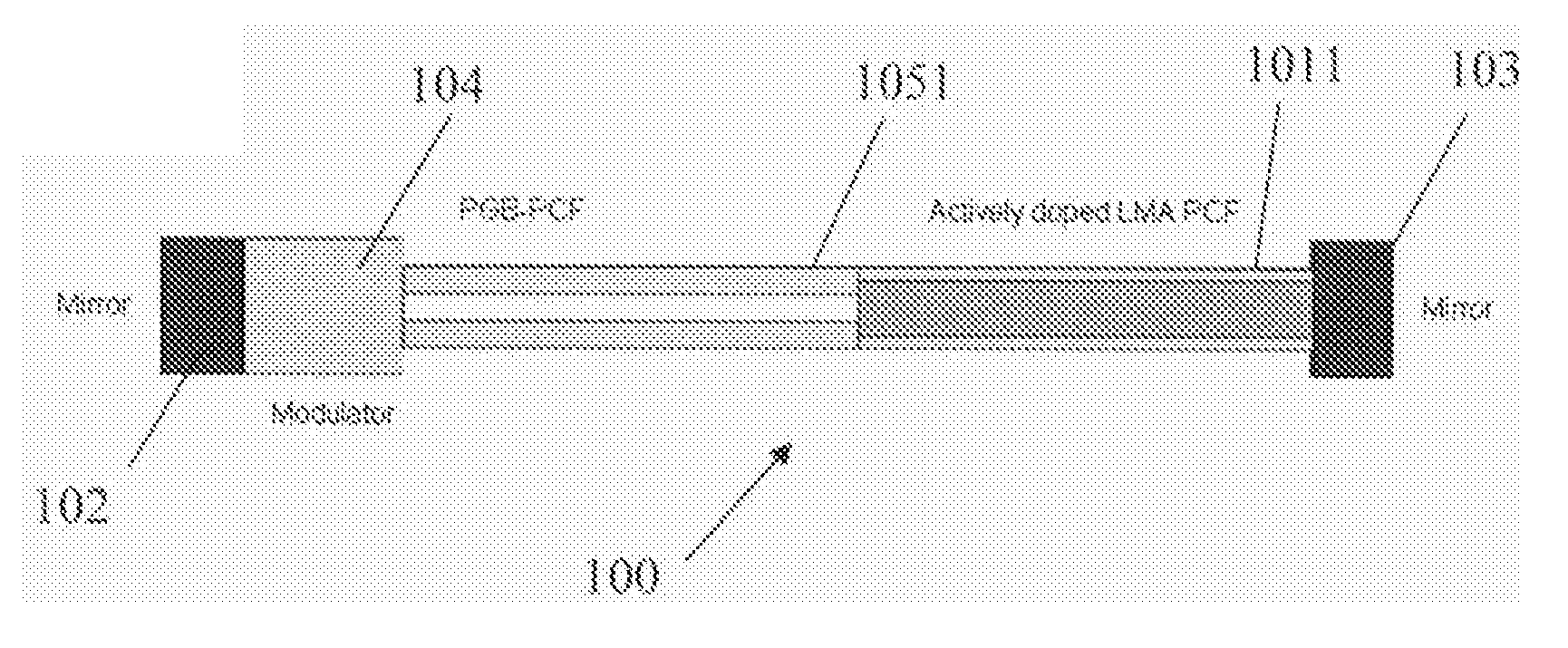
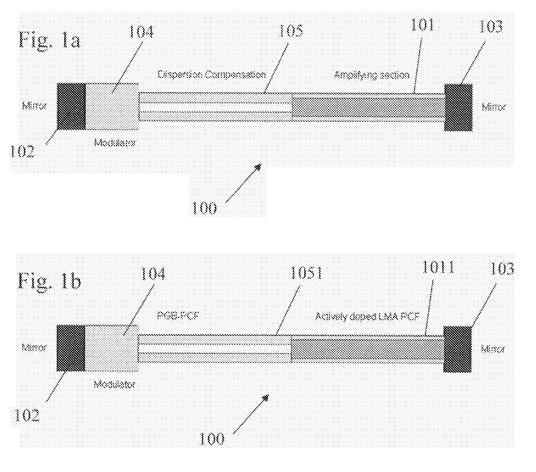
[0152]FIG. 21 shows a block diagram of an all-fiber laser system according to the invention comprising a solid core PBG-fiber (SC-PBG) in the laser cavity.

[0153] The cavity consists of a WDM, 8.5 cm of highly doped ytterbium fiber (1200 dB / m absorption at 976 nm), and a PM 20:80 coupler with PM fiber pigtails (output coupling: 20%), and the 0.36 m of SC-PBG fiber for intra-cavity dispersion compensation. The coupler also works as a polarizer, transmitting only the light in the slow axis, and hence ensures that the output from the cavity i linear polarized. The total length of PM fibers in the cavity was 0.95 m, and the total length of non-PM fibers in the cavity were 0.835 m (including the SC-PBG fiber). The non-PM fibers of the cavity were all kept straight in order to avoid polarization rotation.

[0154] The SC-PBG fiber was spliced to a standard fiber using a standard Ericsson Fusion splicer using an optimized splicing m...


PUM


Abstract

The present invention deals with optical systems for providing short laser pulses. An object of the invention is to provide an optical system providing compact and cost-effective short laser-pulses using fibers with anomalous dispersion and high non-linear thresholds. The object is achieved by a short pulse optical system for generating or processing short laser-pulses, said optical system comprises an optical fiber in the form of a photonic crystal fiber arranged to provide guidance of light in the core region due to the photonic bandgap effect (PBG), where light propagates in a hollow or solid core surrounded by a Silica cladding comprising a substantially periodic distribution of micro-structural elements, and where the refractive index of the core is lower than the effective refractive index of the cladding. The invention may be useful in applications such as laser-based micromachining, thin-film formation, laser cleaning, in medicine and biology.

Description

TECHNICAL FIELD [0001] The present invention relates to optical systems for providing short laser pulses. BACKGROUND OF THE INVENTION [0002] Short optical pulse generation has become an increasingly important technology in recent years in many applications including laser-based micromachining, thin-film formation, laser cleaning, medicine and biology. Exciting results have been demonstrated with ultra-short pulses in ablation of a wide variety of materials with a minimum of thermal or shock damage to the surrounding materials. Examples include dielectrics, e.g. oxide ceramics, optical glasses, polymers, etc. Short pulses are also powerful instrumentals for surface patterning and micro-fabrication due to the non-contact character of material processing. In particular, higher spatial resolution can be achieved with short pulses by reducing heat-affected zone and shock-affected zone (cf. e.g. X. Liu, D. Du, and G. Mourou, “Laser ablation and micromachining with ultrashort laser pulses”...

Claims


Application Information

Patent Timeline
Patent Type & Authority Applications(United States)
IPC IPC(8): H01S3/30H01S3/11H01S3/10G02B6/02G02B6/34H01S3/00H01S3/067H01S3/08H01S3/098H01S3/16
CPCG02B6/02214G02B6/02261G02B6/02328G02B6/02333G02B6/02347G02B6/2552H01S3/0057H01S3/0064H01S3/06725H01S3/06729H01S3/06741H01S3/06745H01S3/06754H01S3/08009H01S3/08059H01S3/094076H01S3/09415H01S3/1063H01S3/1115H01S3/1118H01S3/115H01S3/1611H01S3/1618H01S3/1695H01S3/2308
Inventor PEDERSEN, CLAUS FRIISSKOVGAARD, PETER M.W.
Owner NKT PHOTONICS
Why Eureka
Try Eureka