

Catalytic isobutane alkylation
a technology of isobutane and catalytic isobutane, which is applied in the direction of liquid chemical processes, physical/chemical process catalysts, lighting and heating apparatus, etc., can solve the problems of small leakage, environmental and safety hazards of both systems, and health hazards for plant personnel
- Summary
- Abstract
- Description
- Claims
- Application Information
AI Technical Summary
Benefits of technology
Problems solved by technology
Method used
Image

Examples
Embodiment Construction
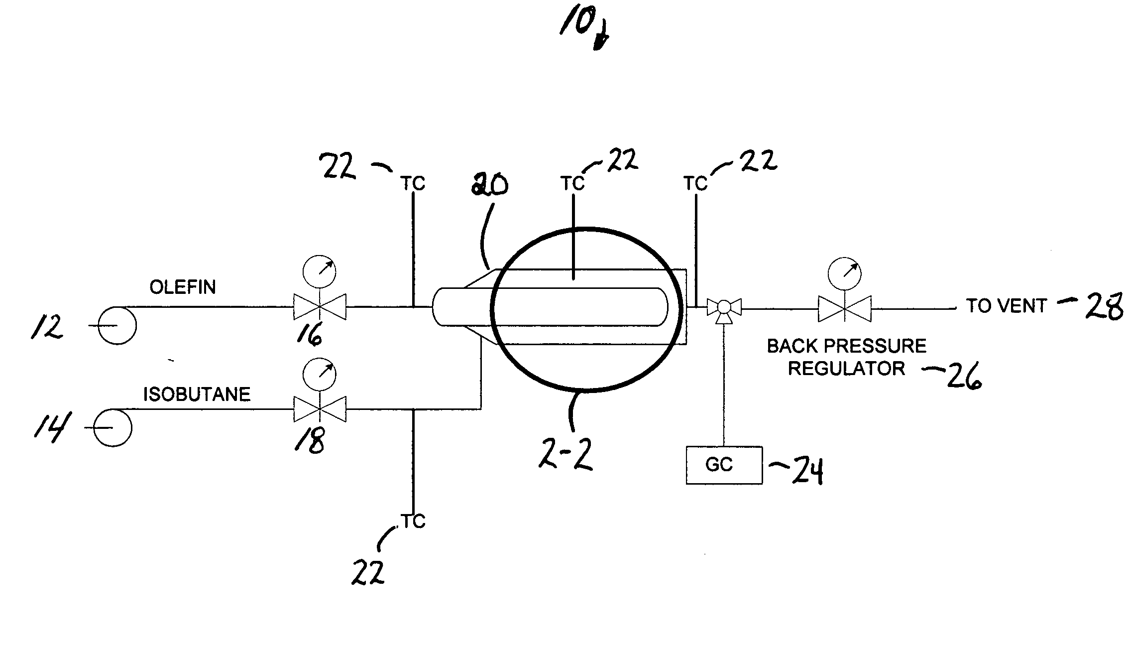
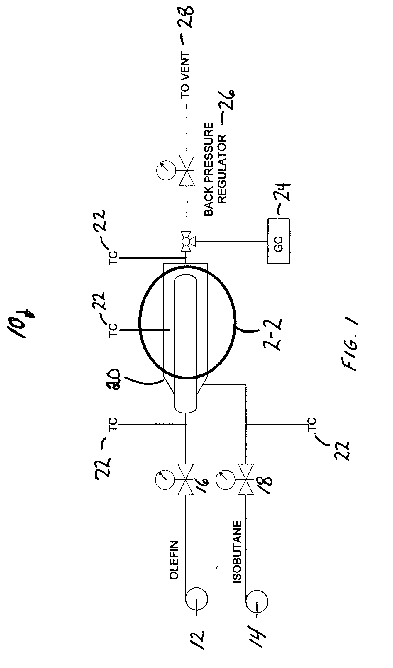
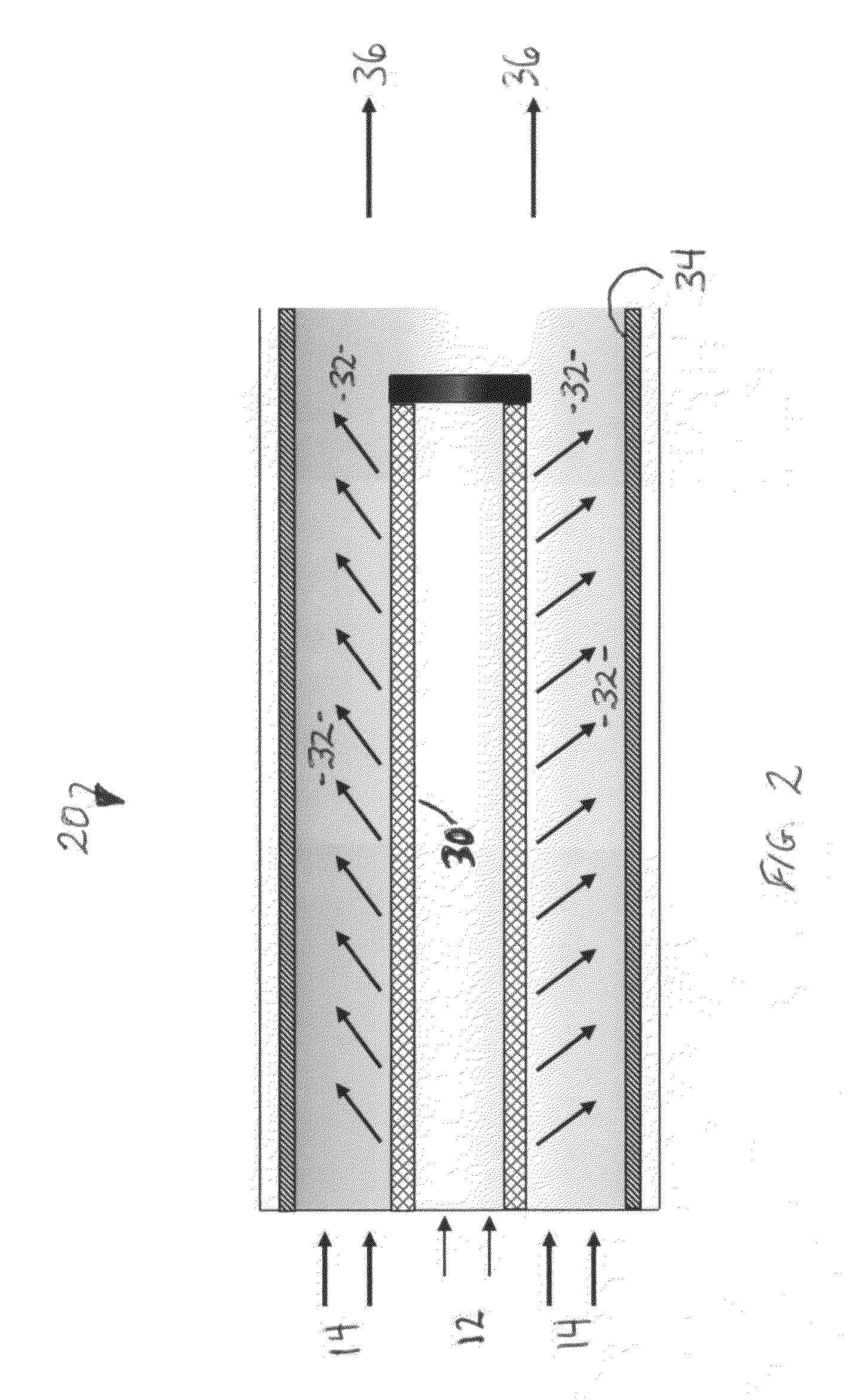
[0009]It has now been found that using a unique reactor design together with controlled addition of olefin, a nominally constant low olefin concentration can be maintained at the catalyst surface. In isobutane alkylation, for example, the effective isobutane-to-olefin surface ratio can even be greater than a thousand-to-one at feed ratios of ten or twenty-to-one.
[0010]Polymer formation on a fixed-bed alkylation catalyst can be reduced to an acceptable level allowing the use of known solid alkylation catalysts at isobutane-to-olefin ratios acceptable in commercial isobutane alkylation. The present invention allows operation even at isobutane-to-olefin ratios lower than those required in current commercial processes. It has now been found that high isobutane ratios on the catalyst surface do not require high isobutane ratios for the feed streams. Although described in terms of isobutane alkylation, the method of the present invention is generic and applies to alkylation of any compoun...
PUM
| Property | Measurement | Unit |
|---|---|---|
| molecular weight | aaaaa | aaaaa |
| concentration | aaaaa | aaaaa |
| surface ratio | aaaaa | aaaaa |
Abstract
Description
Claims
Application Information