Determining Fluid Rate and Phase Information for a Hydrocarbon Well Using Predictive Models

Active Publication Date: 2008-09-25
BP EXPLORATION OPERATING CO LTD
View PDF9 Cites 76 Cited by
  • Summary
  • Abstract
  • Description
  • Claims
  • Application Information

AI Technical Summary

Benefits of technology

[0023]This invention provides a robust method for determining rate and phase information for one or more wells without reliance on continual flow-metering. The wells can be production wells, injection wells or any combination thereof. The method can be used in real time and continuously to provide such rate and phase information. This invention can also be used to alert operators or others of conditions in a well or field to permit more immediate response. This invention also provides methods which are more tolerant of sensor faults, sensor drift, anomalous data or other occurrences which could otherwise lead to incorrect output. This invention also provides a method of using more than one model to permit a hierarchy of calculation such that the rate and phase determination is more tolerant of anomalous data, indeed tolerant of a total failure of a sensor. This invention also provides a method for reconciling rate and phase information calculated from one or more wells with facility data.
[0024]Th

Problems solved by technology

This lack of real-time flow measurements of course reduces confidence in the measurements obtained, and in the decisions made based on those measurements.
In addition to the cumbersome nature of these flow measurements, conventional flow meters generally require frequent calibration to ensure accuracy, considering the typical drift of conventional flow meters over time.
If operating conditions change so that the steady-state condition of a well drifts outside the operating range, the flow measurements can be unreliable.
While recalibration and maintenance of flow meters is somewhat cumbersome for land-based wells, the recalibration and maintenance of flow meters is typically prohibitively difficult and costly in marine environments.
In addition, the inability to service offshore flow meters can cause total loss of flow measurement if a c

Method used


Image

  • Determining Fluid Rate and Phase Information for a Hydrocarbon Well Using Predictive Models
  • Determining Fluid Rate and Phase Information for a Hydrocarbon Well Using Predictive Models
  • Determining Fluid Rate and Phase Information for a Hydrocarbon Well Using Predictive Models

Examples


Embodiment Construction

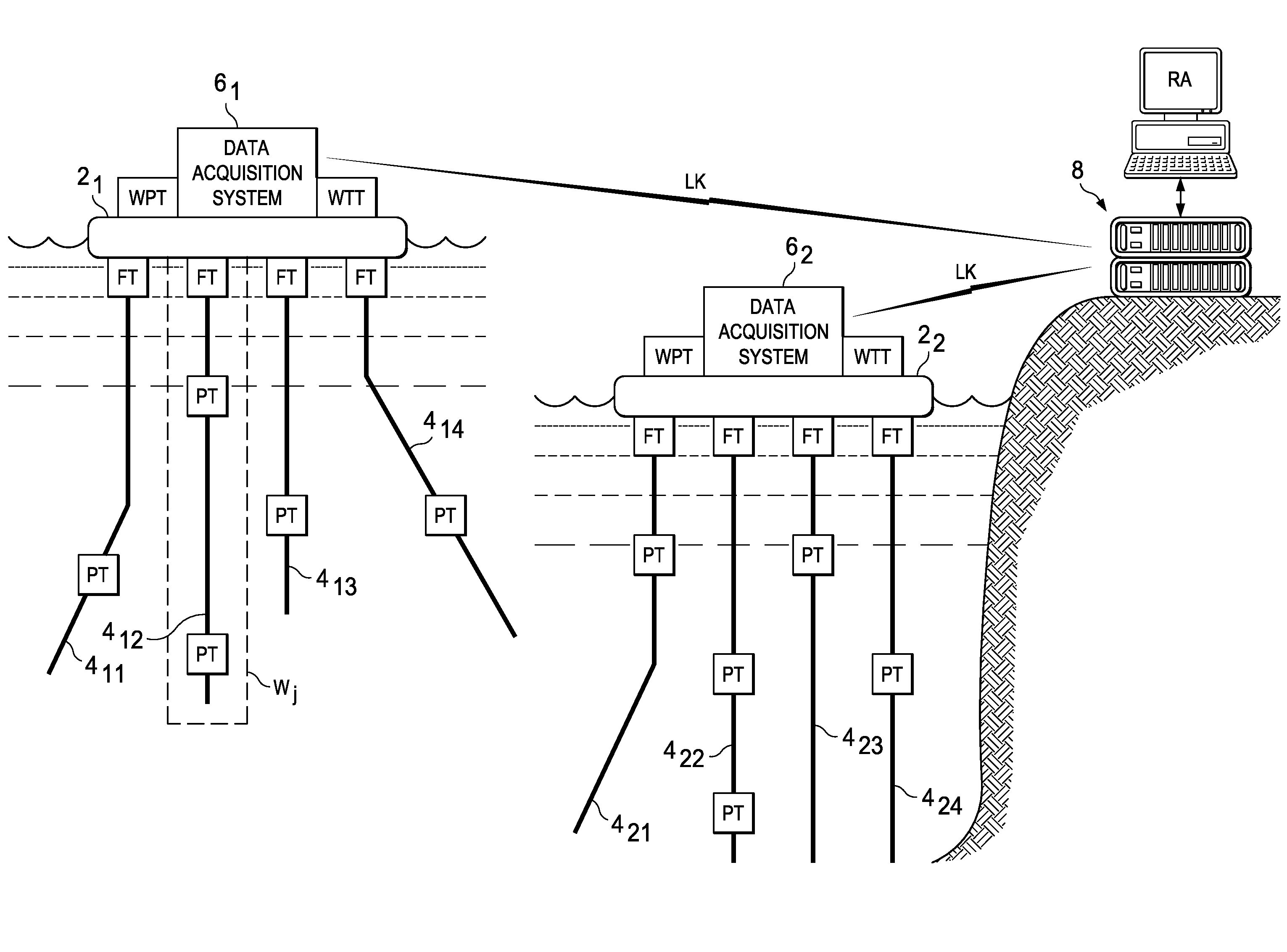
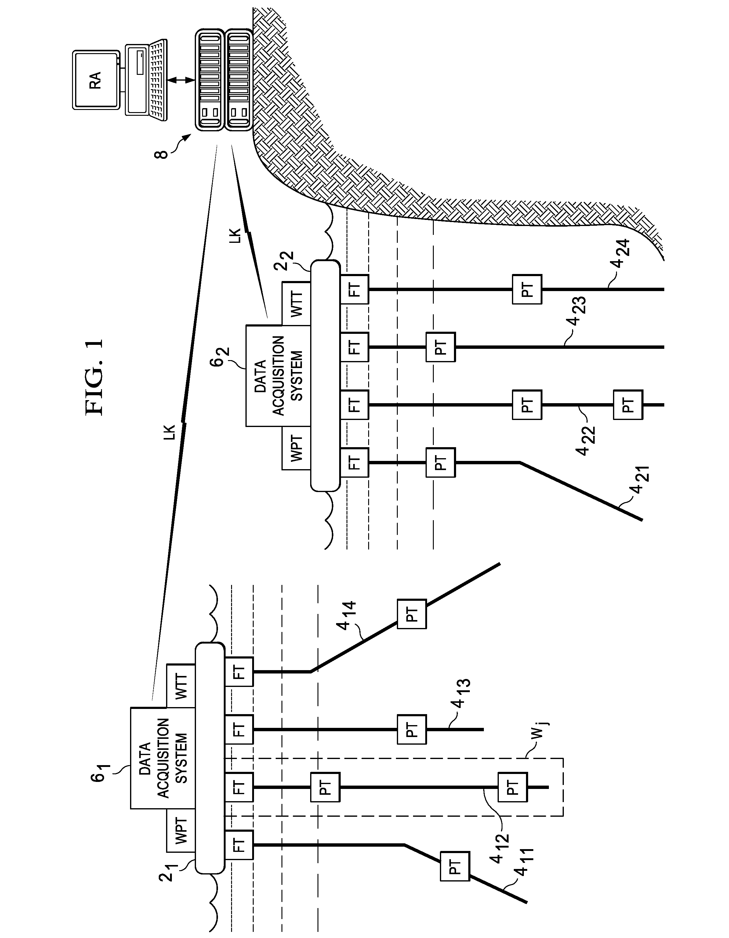
[0041]The present invention will be described in connection with its preferred embodiment, namely as implemented into an existing production field from which oil and gas are being extracted from one or more reservoirs in the earth, because it is contemplated that this invention will be especially beneficial when used in such an environment. However, it is contemplated that this invention may also provide important benefits when applied to other tasks and applications. Accordingly, it is to be understood that the following description is provided by way of example only, and is not intended to limit the true scope of this invention as claimed.

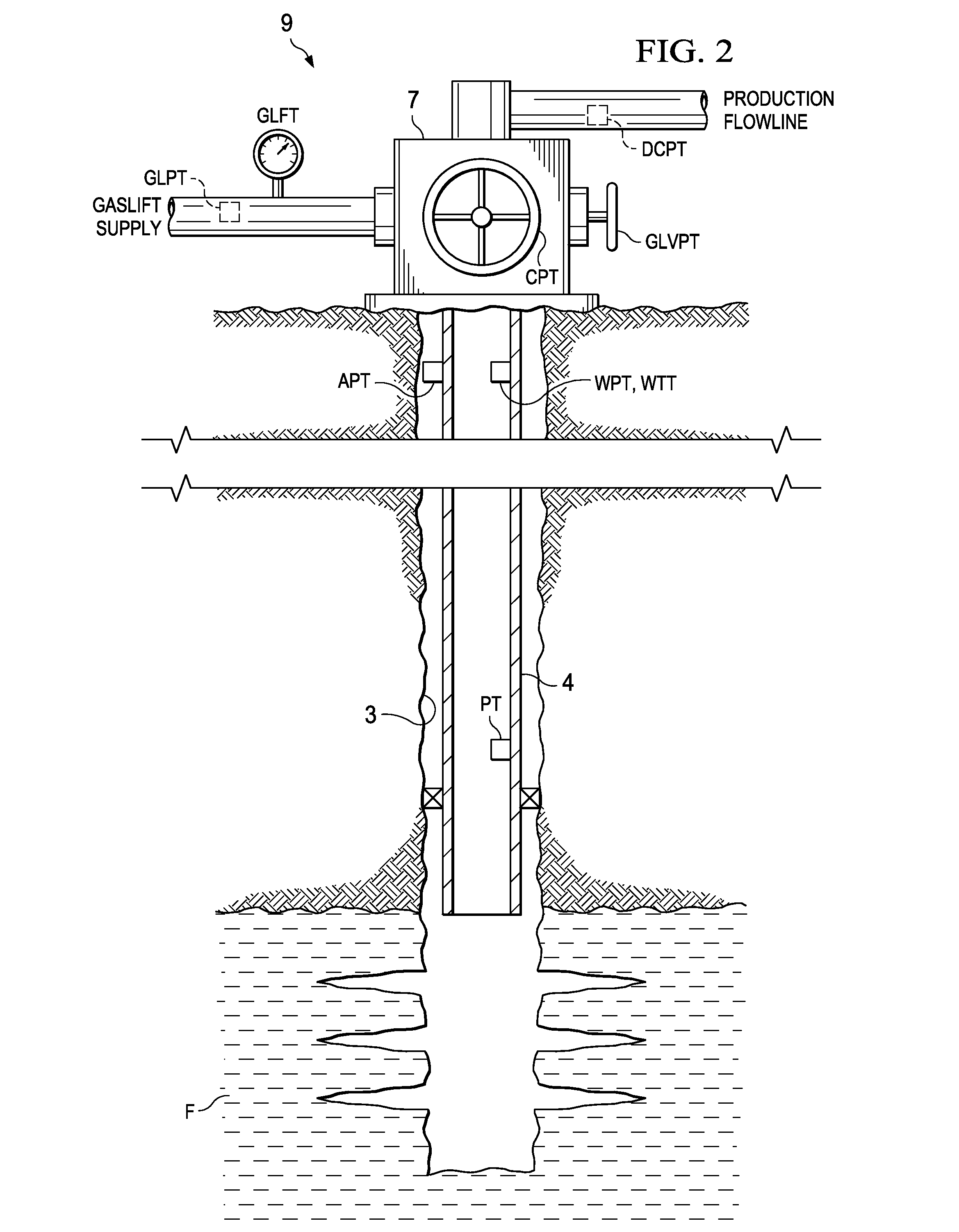
[0042]As will be evident to those skilled in the art having reference to this specification, the preferred embodiments of this invention employ physical models, temperature sensors and pressure sensors, and where applicable, valves and choke positions, to determine the rate and phase of fluid produced from a well. This invention can also provide ...


PUM


Abstract

Physical models of wells are used to determine rate and phase composition for fluid produced from or injected into the wells on a near real time and continuous basis. The method can be used to alert operators or others of conditions in a well or field to permit more immediate response. The method can be more tolerant of sensor faults, sensor drift, anomalous data or other occurrences which could otherwise lead to incorrect output. More than one model can be used to permit a hierarchy of calculation such that the rate and phase determination is more tolerant of anomalous data. The calculated rate and phase values from one or more wells can be reconciled against facility data.

Description

CROSS-REFERENCE TO RELATED APPLICATIONS[0001]This application claims priority, under 35 U.S.C. §119(e), of Provisional Application No. 60 / 891,617, filed Feb. 26, 2007, incorporated herein by this reference.STATEMENT REGARDING FEDERALLY SPONSORED RESEARCH OR DEVELOPMENT[0002]Not applicable.BACKGROUND OF THE INVENTION[0003]This invention is in the field of oil and gas production, and is more specifically directed to the real-time monitoring of fluid flow rates for multiple fluid phases from hydrocarbon wells.[0004]Hydrocarbon production from subterranean reservoirs typically involves multiple wells positioned at various locations of a reservoir. In a given reservoir, the multiple wells are not only deployed at different surface locations, but are also often of different “geometry” from one another, and are also often drilled to different depths. Many typical wells also produce fluids at multiple depths along a single wellbore, thus producing from multiple subsurface strata. As is fund...

Claims


Application Information

Patent Timeline
IPC IPC(8): G01N15/08
CPCE21B43/00E21B47/06G06F17/00G05B17/02G01V11/00E21B47/10
Inventor FOOT, JOHNHEDDLE, RICHARDWEBSTER, MICHAEL J.
Owner BP EXPLORATION OPERATING CO LTD
Why Eureka
Try Eureka