
Fall-away arrow rest

a technology of arrow rests and arrows, which is applied in the direction of spring guns, compressed gas guns, white arms/cold weapons, etc., can solve the problems of fletch may contact the rest, the arrow rest may not be removed, and the flight is disrupted, so as to achieve the effect of smooth operation, easy and quick addition of teflon, and additional quieting and smooth operation

Inactive Publication Date: 2008-10-02
SIMS STEVEN C +4
View PDF31 Cites 17 Cited by
  • Summary
  • Abstract
  • Description
  • Claims
  • Application Information

AI Technical Summary

Benefits of technology

[0009]One important advantage of these arrow rests is that they employ a construction which allows them to be mounted to a wide variety of bows.
[0011]The arrow rests of the present invention are rock solid, and they have bearings which make operation of the rests smooth and quiet.
[0013]The rest is furthermore constructed such that it can be optimally located both vertically and horizontally with respect to the bow when it is mounted to the riser of the bow. This, together with coarse and fine adjustments, allow the initial angle, stroke, and height of the arrow-supporting arm to be adjusted to suit the archer.
[0015]Significant additional quieting and smoothness of operation is obtained by mounting elastomeric shock and vibration dampers to the rest in locations providing for optimum damping.

Problems solved by technology

Shoot-thru rests have the disadvantage that a fletch may contact the rest as the arrow passes through it.
This can disrupt the flight of the arrow, leading to an inaccurate shot, and can damage the fletch.
Also, there is nothing to keep the arrow from falling off the rest.
Some containment rests also allow the fletching to contact the rest, leading to fletch damage and an inaccurate shot when the bow is fired.
Containment rests designed to eliminate fletch-and-rest contact require precise nock and fletching alignment and can be difficult to use.

Method used


Image

  • Fall-away arrow rest
  • Fall-away arrow rest
  • Fall-away arrow rest

Examples


Embodiment Construction

[0028]Important features of the present invention are described below with reference to the drawings. This list is not to be taken as all-inclusive.

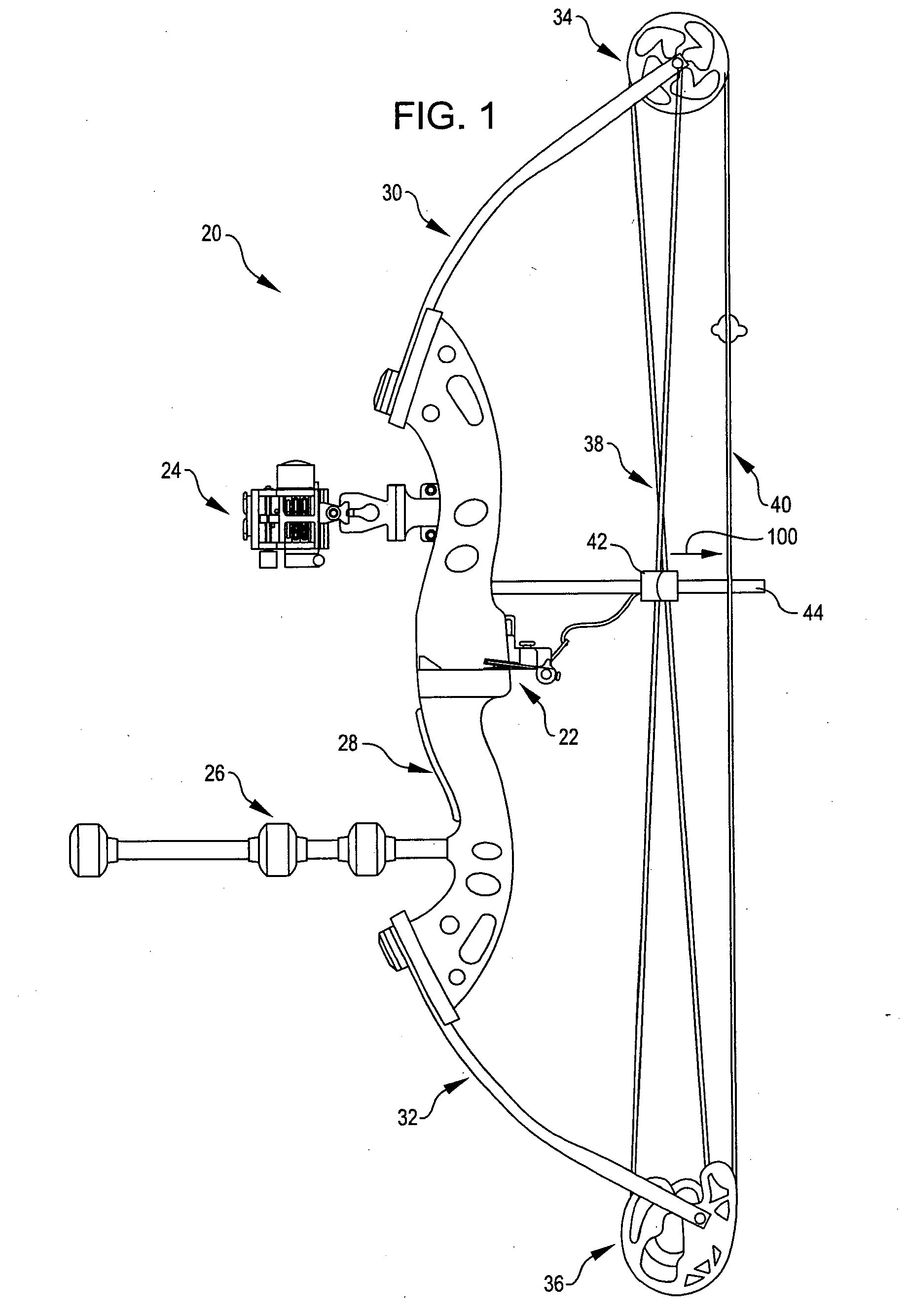
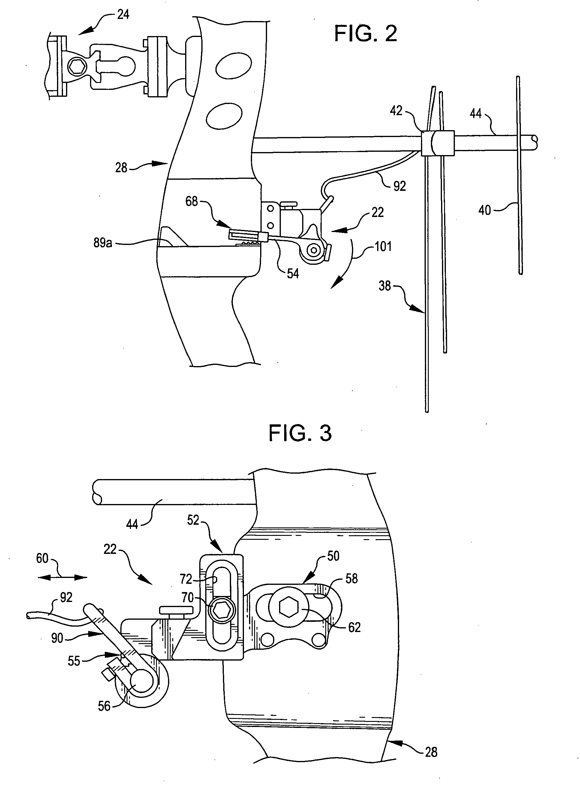
[0029]Referring now to the illustrations, FIGS. 1 and 2 depict a compound bow 20 equipped with a fall-away arrow rest 22, an optical sight 24, and a modular stabilizer 26.

[0030]Bow 20 is of conventional construction. It has a riser 28, upper and lower limbs 30 and 32, cams 34 and 36 at the far ends of limbs 30 and 32, buss cables (collectively identified by reference character 38), a bow string 40, and a cable slide 42 mounted on an elongated guide 44.

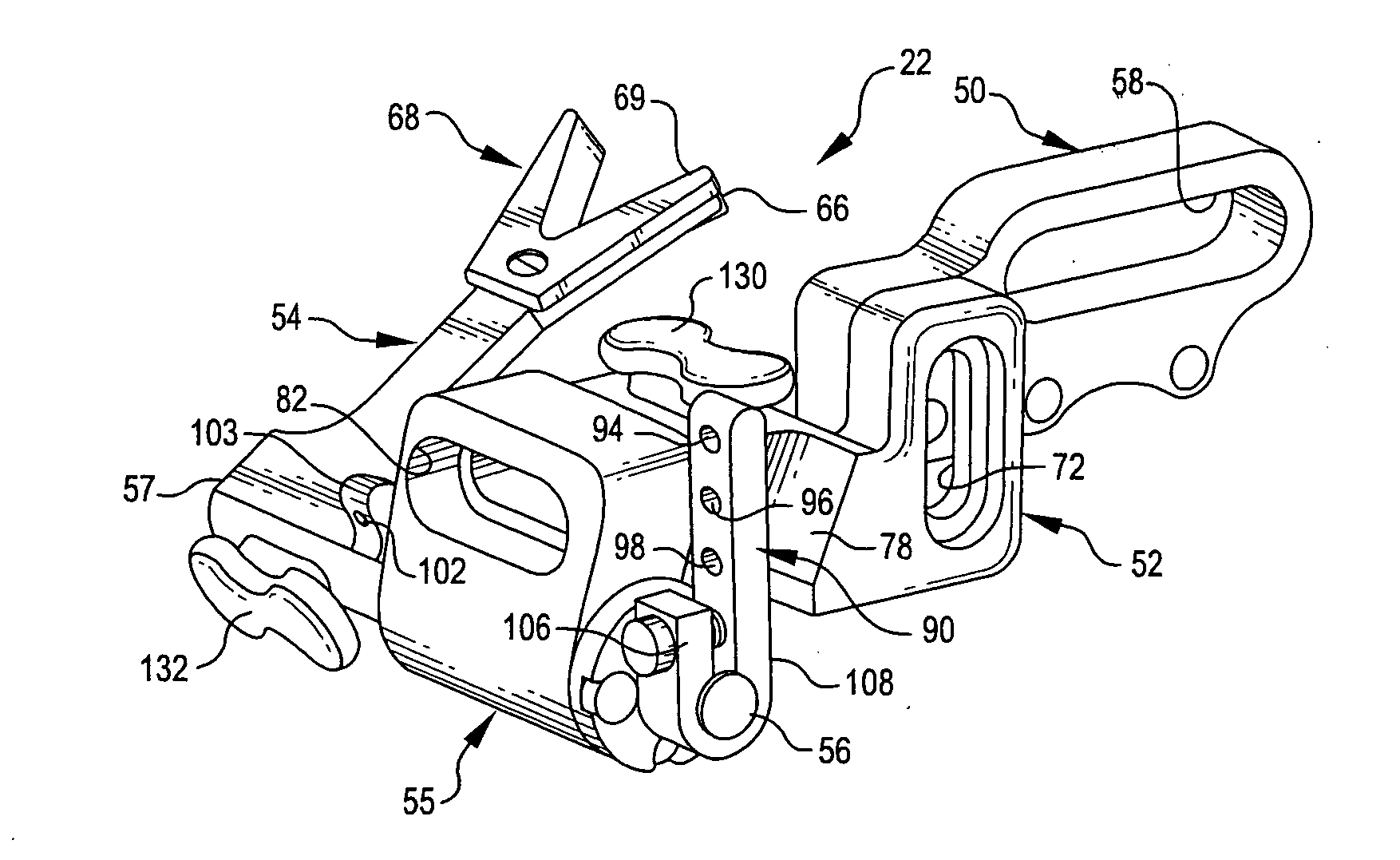
[0031]Arrow rest 22 includes brackets 50 and 52, an arrow support and stabilizing arm 54, an axle housing 55, and a transversely extending axle (or shaft) 56, which is rotatable in but fixed lengthwise of housing 55. The proximate end 57 of arm 54 is assembled to axle 56 for rotation therewith.

[0032]An elongated slot 58 in support bracket 50 allows the rest to be adjusted in a fore-and-aft ...


PUM


Abstract

Fall away arrow rests for archery bows. The rests have an arm with an arrow-supporting feature and an arm-associated axle which pivots the arm to displace the arrow-supporting feature between a first, arrow-loading position and a second, more elevated, arrow-launching position. The arrow support arm can be adjusted vertically, laterally, and in fore-and-aft directions relative to a riser or other rigid bow component on which the rest is mounted. Radial arms rotatable with the axle and connectable to a buss cable or cable slide by a flexible link rotate the arm to elevate the arrow-supporting feature to its arrow-launching when the bow is drawn and offer further adjustment of the arrow rest operation. A coil spring installed in an axle housing returns the arrow-supporting feature to its first, loading position concomitantly with arrow launch, moving the support out of the path the arrow travels as it leaves the bow. Axle-associated stops automatically stop the arm-associated axle as the arrow-supporting feature respectively reaches its arrow-launching and arrow-loading positions. One or more dampers can be advantageously attached to arrow rest structural members to reduce shock and vibrations, including noise, as the arrow support arm displaces the arrow-supporting feature between its first and second positions, especially as an arrow is launched from the bow. Noise reduction can be furthered by a installing a Teflon or comparable component on the arrow-supporting feature of the arm and / or by installing an elastomeric pad on the rigid bow component in the path followed by the arrow-supporting feature as that feature approaches its arrow-loading position.

Description

CROSS-REFERENCE TO A RELATED APPLICATION[0001]The priority of provisional application No. 60 / 879,909 is claimed.TECHNICAL FIELD OF THE INVENTION[0002]The present invention relates to novel, improved arrow rests for compound bows.BACKGROUND OF THE INVENTION[0003]Arrow rests are employed to hold the arrow in position until a bow is fired. This makes for a more accurate shot than positioning the arrow with the archer's hand does.[0004]Three types of arrow rests are available: shoot-thru, containment, and fall-away.[0005]Shoot-thru rests have the disadvantage that a fletch may contact the rest as the arrow passes through it. This can disrupt the flight of the arrow, leading to an inaccurate shot, and can damage the fletch. Also, there is nothing to keep the arrow from falling off the rest.[0006]Some containment rests also allow the fletching to contact the rest, leading to fletch damage and an inaccurate shot when the bow is fired. Containment rests designed to eliminate fletch-and-rest...

Claims


Application Information

Patent Timeline
IPC IPC(8): F41B5/22F41B5/10
CPCF41B5/10F41B5/143F41B5/1426
Inventor SIMS, STEVEN C.CLARK, GEORGEEASTMAN, SCOTTSELL, JOHNATHAN F.WINTERS, GREG
Owner SIMS STEVEN C
Learn More