Plasma processing apparatus

Active Publication Date: 2008-10-02
TOKYO ELECTRON LTD
View PDF3 Cites 18 Cited by
  • Summary
  • Abstract
  • Description
  • Claims
  • Application Information

AI Technical Summary

Benefits of technology

[0009]The present invention provides a plasma processing apparatus which is capable of, over a prolonged period of time, controlling a decrease in the value of a DC current flowing within an accommodating compartment.

Problems solved by technology

As a result, plasma within the accommodating compartment may fall into an unstable state or plasma treatment characteristics may change.
However, it has been confirmed by the present inventor that if the total time of a plasma treatment exceeds, for example, 70 hours, the value of a DC current flowing within the accommodating compartment decreases to 1.43 A to 1.33 A. Thus, there is the problem that a decrease in the value of a DC current causes a change in plasma treatment characteristics.

Method used


Image

  • Plasma processing apparatus
  • Plasma processing apparatus
  • Plasma processing apparatus

Examples


example 1

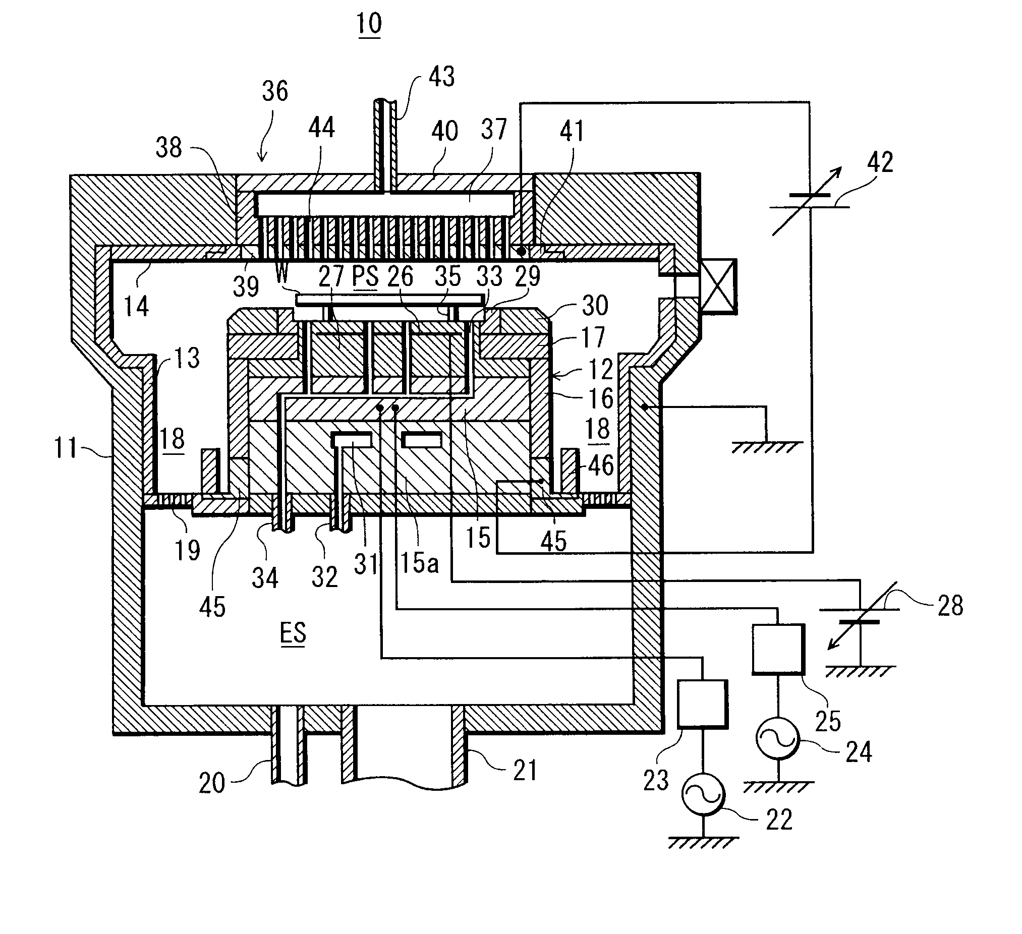
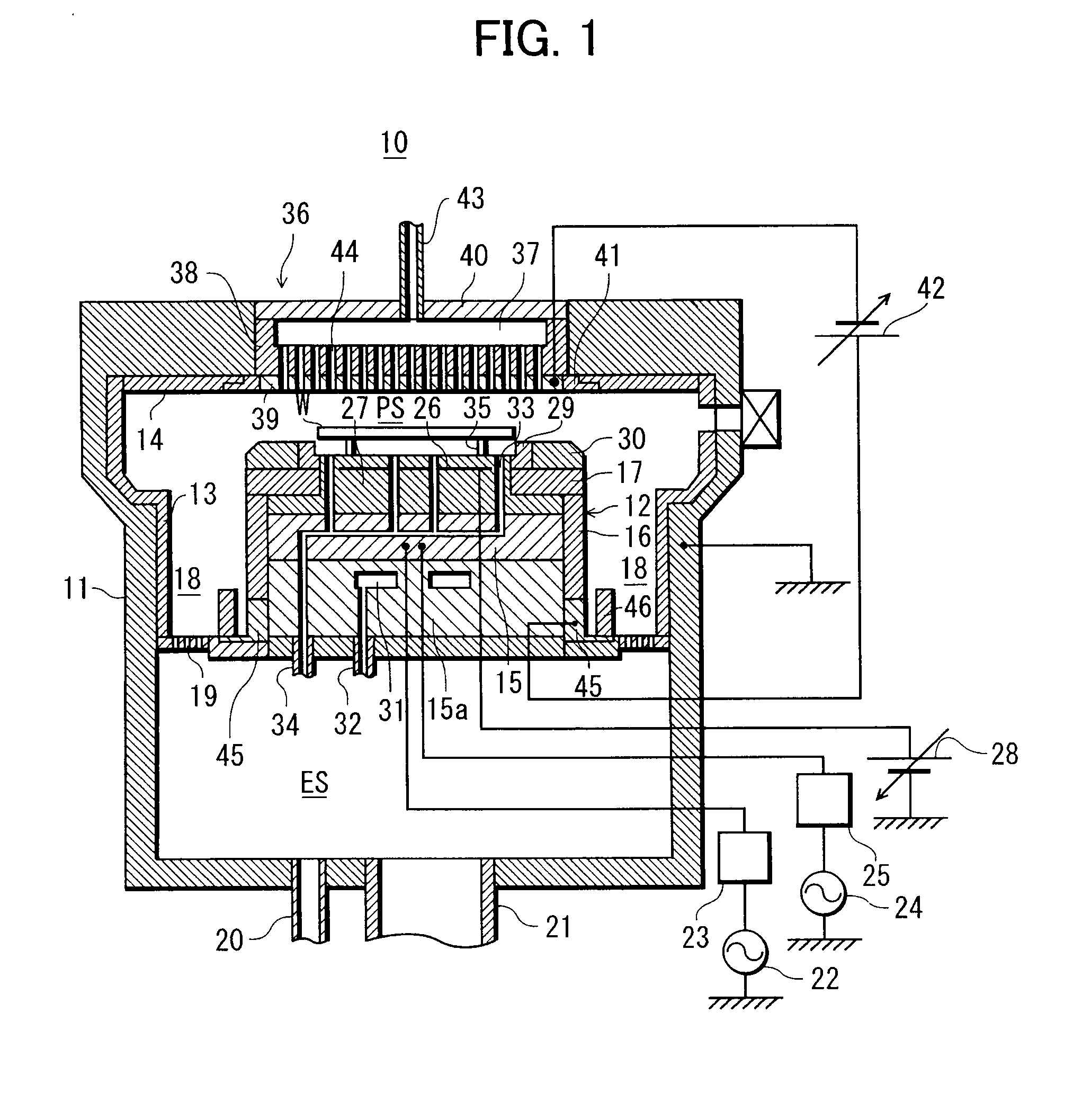
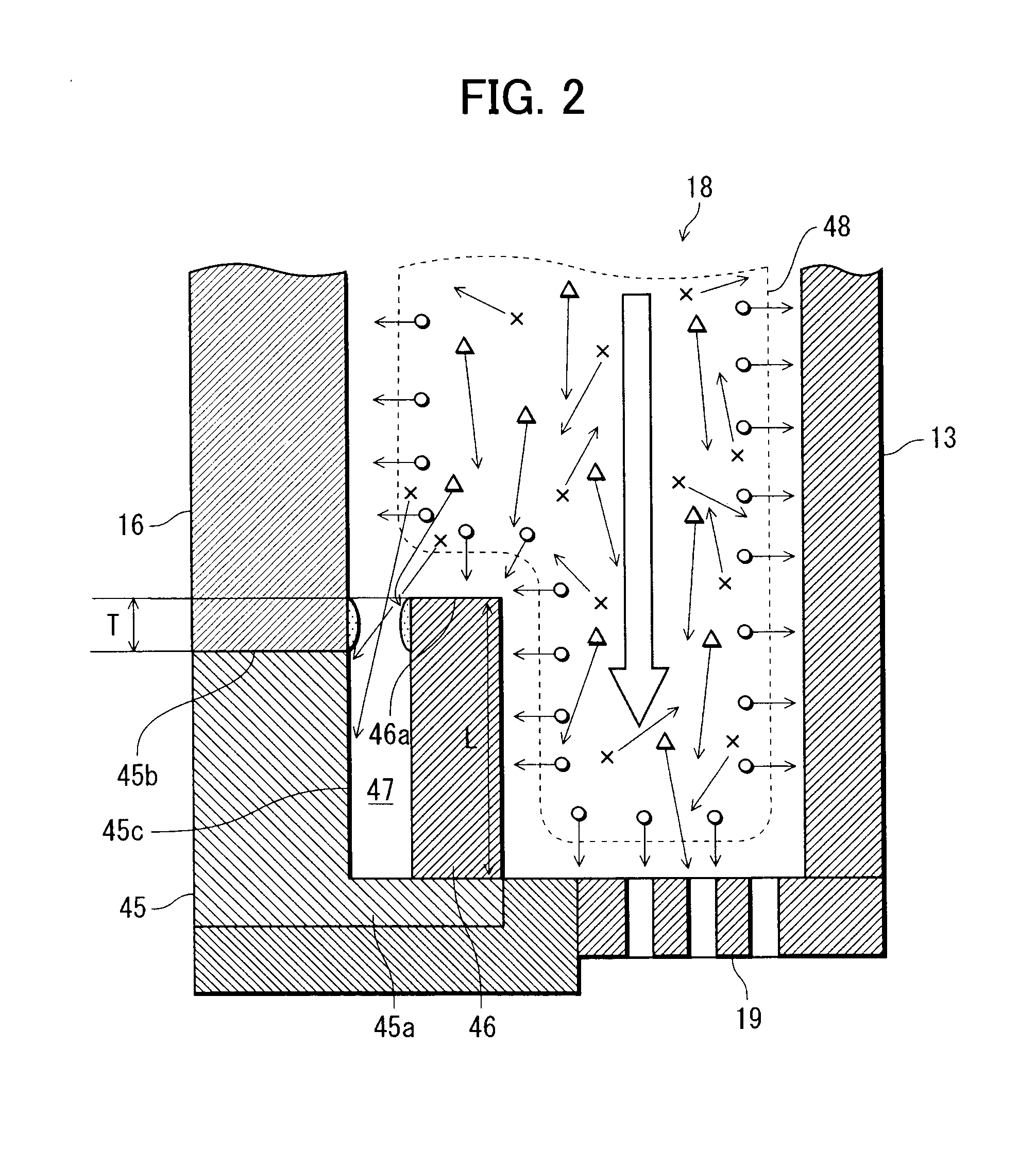
[0078]In the plasma processing apparatus 10, a gap “t” between the ground electrode surface 45c of a grounding ring 45 and a shielding member 46 was set to 2.5 mm, and the amount of protrusion “T” of the edge 46a of the shielding member 46 on the opening side thereof from the edge 45b of the grounding ring 45 on the opening side thereof (see FIG. 2—hereinafter simply referred to as the “protruding amount “T” of the shielding member 46”) was set to 0 mm.

[0079]After that, an etching treatment on a wafer W was repeated in the plasma processing apparatus 10. In each case of etching treatment, a DC current flowing through a processing space PS was measured and the measured values of the DC current were shown by “X” in the graph of FIG. 4. Then, a calculation was made of an approximate expression of the rate of decrease in the value of the DC current (hereinafter simply referred to as the “decrease rate”) for Example 1 in the graph of FIG. 4, thus obtaining Equation (1) shown below:

DC cur...

example 2

[0080]In a plasma processing apparatus 10, a gap “t” was set to 3.5 mm and the protruding amount “T” of a shielding member 46 was set to 3.0 mm.

[0081]After that, an etching treatment on a wafer W was repeated in the plasma processing apparatus 10, as in Example 1. In each case of etching treatment, a DC current flowing through a processing space PS was measured and the measured values of the DC current were shown by “Δ” in the graph of FIG. 4. Then, a calculation was made of an approximate decrease rate expression for Example 2, thus obtaining Equation (2) shown below

DC current value=−6.04×10⁻⁶×number of treated wafers+1.39  (2)

[0082]where, the term “−6.04×10⁻⁶” corresponds to the decrease rate (degradation rate).

example 3

[0086]In a plasma processing apparatus 10, a gap “t” was set to 4.0 mm and the protruding amount “T” of a shielding member 46 was set to 3.0 mm.

[0087]After that, an etching treatment on a wafer W was repeated in the plasma processing apparatus 10, as in Example 1. In each case of etching treatment, a DC current flowing through a processing space PS was measured and the measured values of the DC current were shown by “□” in the graph of FIG. 5.


PUM

PropertyMeasurementUnit
Lengthaaaaaaaaaa
Lengthaaaaaaaaaa
Lengthaaaaaaaaaa

Abstract

A plasma processing apparatus capable of, over a prolonged period of time, controlling a decrease in the value of a DC current flowing within an accommodating compartment. The plasma processing apparatus comprises an accommodating compartment adapted to accommodate a substrate and perform a plasma treatment thereon, a high-frequency power source adapted to supply high-frequency power to the inside of the accommodating compartment; a DC electrode adapted to apply a DC voltage to the inside of the accommodating compartment, a ground electrode provided within the accommodating compartment and used for the applied DC voltage, and an exhaust unit adapted to evacuate the inside of the accommodating compartment. The plasma processing apparatus further comprises a shielding member disposed in the accommodating compartment so as to extend along the flow of exhaust gas, interpose between the flow of exhaust gas and the ground electrode, and form a cross-sectionally elongated groove-shaped space between the shielding member and the ground electrode.

Description

BACKGROUND OF THE INVENTION[0001]1. Field of the Invention[0002]The present invention relates to a plasma processing apparatus and, more particularly, to a plasma processing apparatus having an electrode connected to a DC power source.[0003]2. Description of the Related Art[0004]There is known a parallel plate type plasma processing apparatus provided with an accommodating compartment for accommodating a wafer serving as a substrate, a lower electrode disposed within the accommodating compartment and connected to a high-frequency power source, and an upper electrode disposed so as to face the lower electrode. In this plasma processing apparatus, a processing gas is introduced into the accommodating compartment and high-frequency power is supplied into the accommodating compartment. In addition, plasma is produced from the introduced processing gas by the high-frequency power when the wafer is accommodated into the accommodating compartment and mounted on the lower electrode. Thus, a...

Claims


Application Information

Patent Timeline
IPC IPC(8): C23C16/503
CPCH01J37/32091H01J37/3244H01J37/32559H01J37/32623H01J37/32633H01J37/32834H01J37/32651
Inventor HONDA, MASANOBU
Owner TOKYO ELECTRON LTD
Why Eureka
Try Eureka