Piezoelectric element and its manufacturing method

Inactive Publication Date: 2008-10-02
SEIKO EPSON CORP
View PDF0 Cites 17 Cited by
  • Summary
  • Abstract
  • Description
  • Claims
  • Application Information

AI Technical Summary

Benefits of technology

[0009]In accordance with an advantage of some aspects of the invention, piezoelectric elements with red

Problems solved by technology

One of the primary causes that increase the leakage current is moisture in the air-atmosphere that adheres to side surfaces of piezoelectric elements.
When moisture in the air-atmosphere adheres to side surfaces of a piezoelectric element, it is possible that leakage current is generated as it runs along the side surfaces, which may eventually develop into di

Method used


Image

  • Piezoelectric element and its manufacturing method
  • Piezoelectric element and its manufacturing method
  • Piezoelectric element and its manufacturing method

Examples


Example

[0027]Preferred embodiments of the invention are described below with reference to the accompanying drawings. It is noted that the embodiment described below is an example of the invention.

[0028]1. Piezoelectric Element

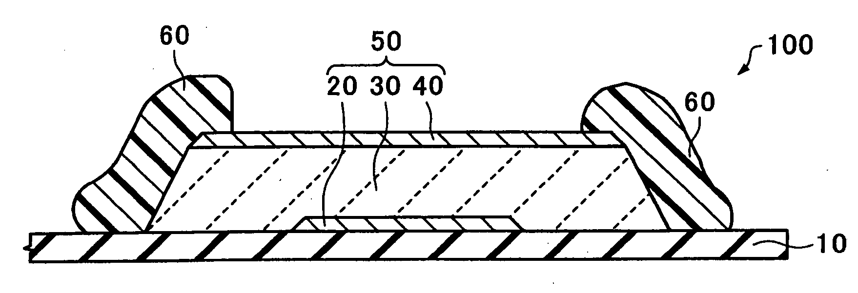
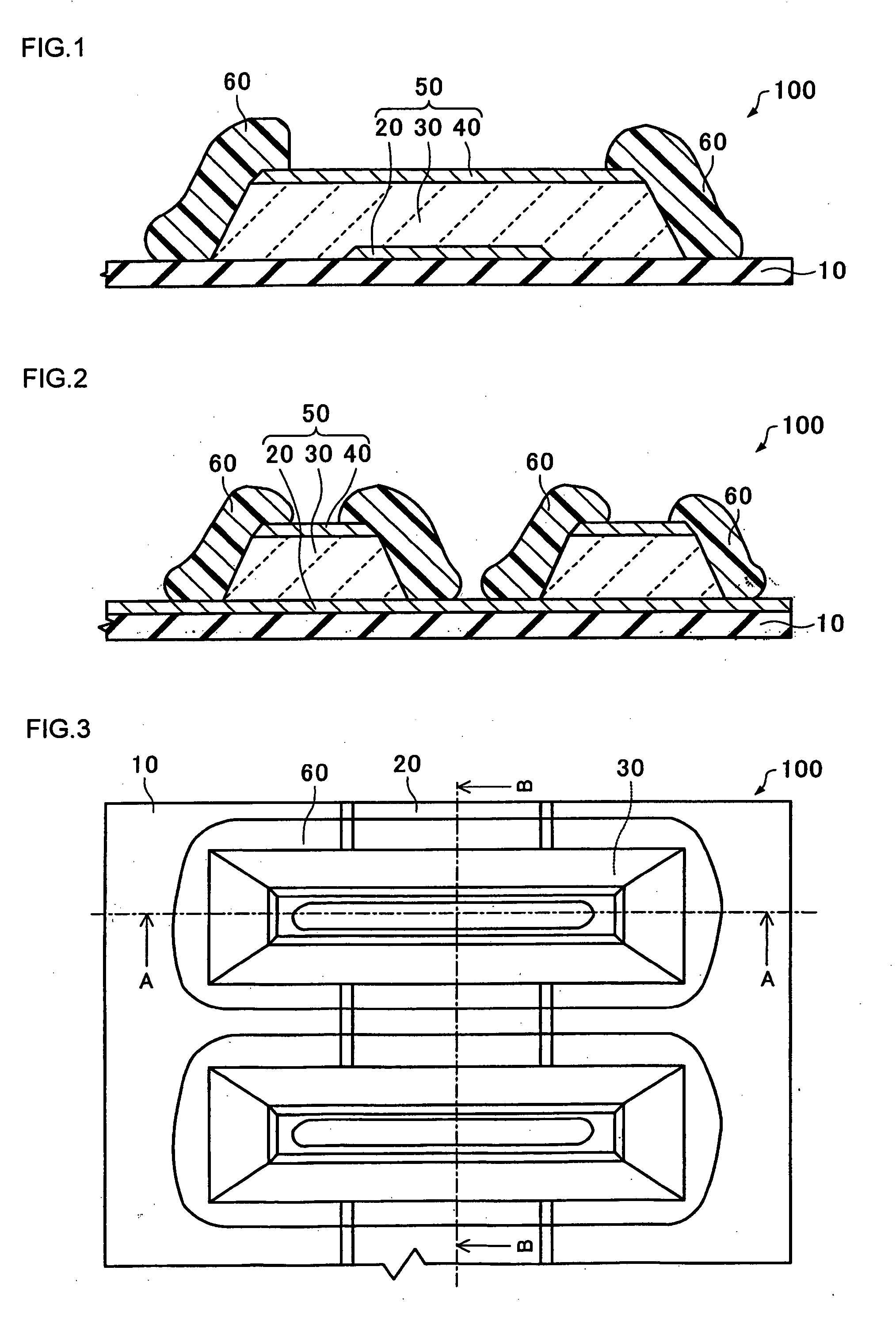
[0029]FIG. 1 is a schematic cross-sectional view of a piezoelectric element 100 in accordance with an embodiment of the invention. FIG. 2 is a schematic cross-sectional view of the piezoelectric element 100 in accordance with the embodiment of the invention. FIG. 3 is a schematic plan view of the piezoelectric element 100 in accordance with the embodiment of the invention. FIG. 1 and FIG. 2 are cross-sectional views taken along a line A-A and a line B-B of FIG. 3, respectively.

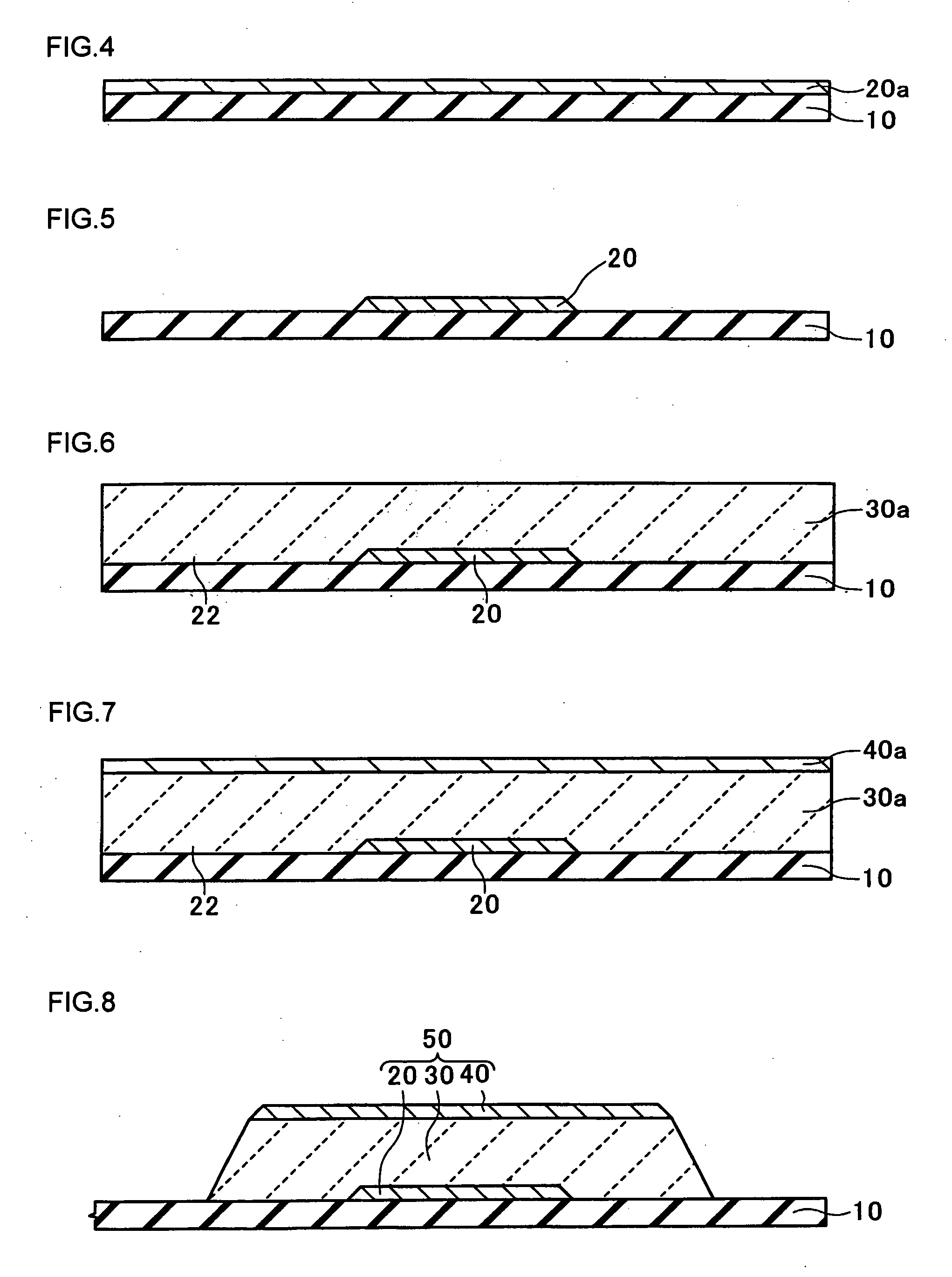
[0030]The piezoelectric element 100 includes a base substrate 10, a lower electrode 20, a piezoelectric layer 30, an upper electrode 40 and a protection layer 60.

[0031]The base substrate 10 is a member that provides mechanical outputs when the piezoelectric element 100 is operated. The base subs...


PUM


Abstract

A piezoelectric element includes: a base substrate; a lower electrode provided on the base substrate; a piezoelectric layer provided on the lower electrode; an upper electrode provided on the piezoelectric layer; and a protection layer that covers a side surface of the piezoelectric layer, wherein the protection layer is formed from polymeric material.

Description

[0001]The entire disclosure of Japanese Patent Application No. 2007-087576, filed Mar. 29, 2007 is expressly incorporated by reference herein.BACKGROUND[0002]1. Technical Field[0003]The present invention relates to piezoelectric elements, and methods for manufacturing the same.[0004]2. Related Art[0005]In general, piezoelectric elements have a structure in which a piezoelectric composed of inorganic oxide is interposed between two electrodes. The piezoelectric element is capable of electromechanical conversion in which deformation is generated in the piezoelectric by applying an electric filed across the electrodes. The piezoelectric expands and contracts according to electrical signals applied through the electrodes. Polycrystal sintered materials such as lead zirconate titanate (PZT) may be representative as the piezoelectric materials. The thickness of the piezoelectric layer is generally set to 500 nm -1500 nm in order to maintain its mechanical reliability. When an operation vo...

Claims


Application Information

Patent Timeline
IPC IPC(8): H01L41/08H01L41/22B41J2/14B41J2/16H01L41/09H01L41/187H01L41/23H02N2/00
CPCH01L41/0533H01L41/0973H01L41/23H10N30/883H10N30/2047H10N30/02
Inventor OHASHI, KOJIKONISHI, AKIO
Owner SEIKO EPSON CORP
Why Eureka
Try Eureka