This helps you quickly interpret patents by identifying the three key elements:
Problems solved by technology
Method used
Benefits of technology
Benefits of technology
[0005]Varistors can protect electronic elements, such as a semiconductor light emitting element and an FET (Field EffectTransistor), from ESD (Electrostatic Discharge) surges when connected in parallel to the electronic elements. The electronic elements include ones which generate heat during their operation. High temperature state of the electronic element causes deterioration in characteristics of the element itself, and thereby affecting its operation. Therefore it is necessary to radiate the generated heat efficiently.
[0006]The present invention has been accomplished in order to solve the above problem and an object of the invention is to provide a varistor and a light emitting device capable of efficiently radiating heat.
Problems solved by technology
High temperature state of the electronic element causes deterioration in characteristics of the element itself, and thereby affecting its operation.
However, when the metal is brought into contact with one surface of the outer side of the varistor element body, the bonding strength between them is weak, and thereby in some cases, the varistor element body and the metal are separated from each other In this case, heat conducted from the metal portion to the varistor cannot be radiated efficiently.
Method used
Image
Click on the blue label to locate the original text in one second.
Reading with bidirectional positioning of images and text.
Examples
second embodiment
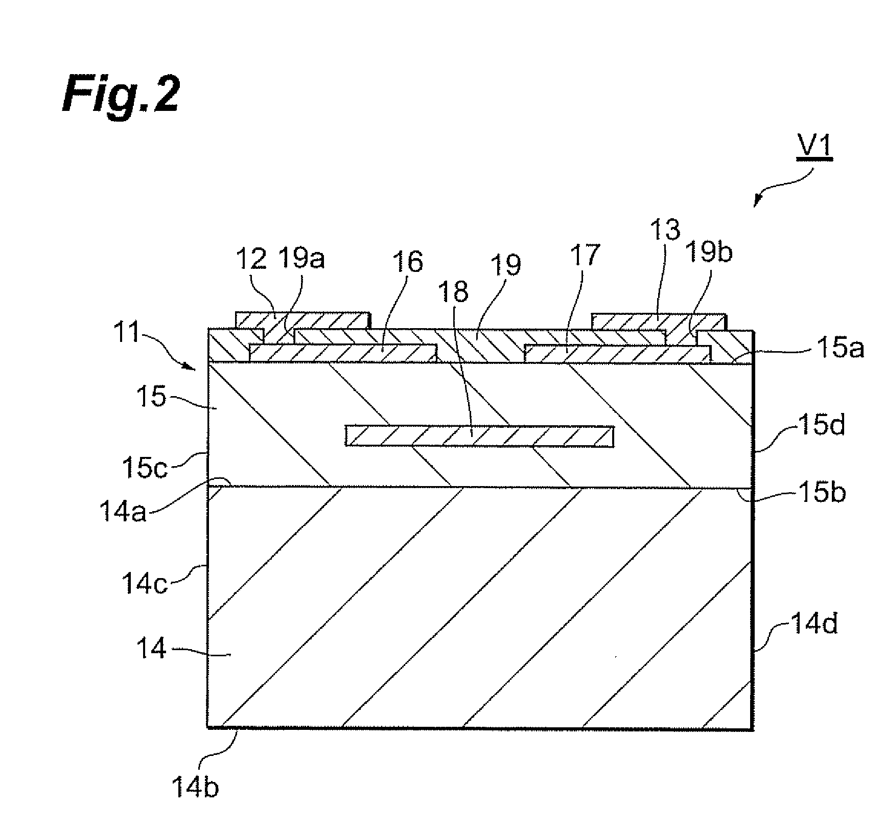
[0048](Second Embodiment) A varistor in accordance with a second embodiment of the present invention, will be described, FIG. 3 is a schematic cross-sectional view illustrating the varistor in accordance with the present invention. The varistor V2 illustrated in FIG. 3 differs from the varistor V1 in accordance with the first embodiment, in the configuration of the internal electrodes thereof.
[0049]In other words, the varistor V2 is not provided with a third internal electrode 18 (refer to FIG. 2), and instead, it includes a first internal electrode 21 and a second internal electrode 22 arranged inside a varistor element body 15 so that one-end sides thereof face each other. In addition, the first internal electrode 21 and the second internal electrode 22 are connected to the external electrodes 12 and 13 by each of penetrating conductors 23, respectively.
[0050]In the varistor V2, the varistor element body 15 also contains composed ZnO as a main component, and the heat radiating por...
third embodiment
[0051](Third Embodiment) A varistor in accordance with a third embodiment of the present invention, will be described. FIG. 4 is a schematic cross-sectional view illustrating the varistor in accordance with the present invention. The varistor V3 illustrated in FIG. 4, further differs from the varistor V2 in accordance with the second embodiment, in that glaze 31 is also formed at the side of the surface 14b not contacting with the varistor portion 11 in the heat radiating portion 14.
[0052]In the varistor V3, the varistor element body 15 also contains ZnO as a main component, and the heat radiating portion 14 is formed with a composite material of metal Ag and metal oxides containing ZnO that is the main component of the varistor element body 15. Therefore, the bonding strength between the varistor portion 11 and the heat radiating portion 14 is sufficiently ensured, and heat conducted to the varistor portion 11 from an external element via the external electrodes 12 and 13, is radia...
fourth embodiment
[0053](Fourth Embodiment) A varistor in accordance with a fourth embodiment of the present invention, will be described, FIG. 5 is a schematic cross-sectional view illustrating the varistor in accordance with the present invention. The varistor V4 illustrated in FIG. 5 further differs from the varistor V3 in accordance with the third embodiment, in that additional external electrodes 41 and 42 are formed on the outer surface of the glaze 31 formed at the side of the surface 14b not contacting with the varistor portion 11.
[0054]In the varistor V4, one external electrode 12 formed at the side of the varistor portion 11, a first internal electrode 21, and one external electrode 41 formed at the side of the heat radiating portion 14 are connected by a penetrating electrode 43, and further, the other external electrode 13 formed at the side of the varistor portion 11, a second internal electrode 22, and the other external electrode 42 formed at the side of the heat radiating portion 14 a...
PUM
Abstract
In a varistor, a heat radiating portion contains the same components as ZnO that is the main component of a varistor element body, as metal oxides, thereby, the structural components of the varistor element body and the heat radiating portion are caused to be common. During firing, Ag contained in the heat radiating portion diffuses into the grain boundaries of ZnO, near the interface between surfaces of the heat radiating portion and the varistor element body. Consequently, in the varistor, cracks hardly occur between the varistor portion and the heat radiating portion during firing (or during binder removal), thereby, ensuring sufficient bonding strength between the varistor portion and the heat radiating portion. Therefore, heat conducted to the varistor portion is radiated efficiently conducting through electrically conducted paths formed in the heat radiating portion from the surface facing the varistor element body to other three surfaces of the heat radiating portion.
Description
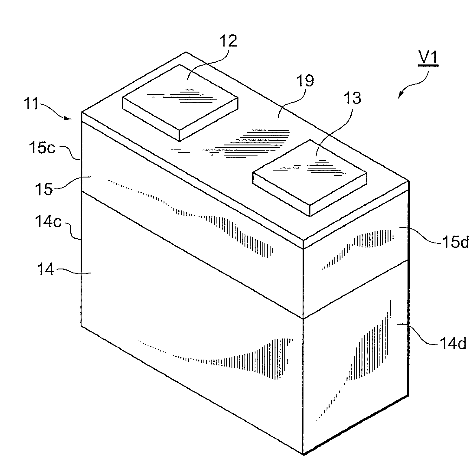
BACKGROUND OF THE INVENTION[0001]1. Field of the Invention[0002]The present invention relates to a varistor and a light emitting device having the same.[0003]2. Related Background Art[0004]There is a varistor including an element body having a varistor element body exhibiting voltage nonlinearity and a pair of internal electrodes arranged inside the varistor element body with sandwiching a part of the varistor element body between the internal electrodes, and a pair of terminal electrodes formed on an outer surface of the element body and respectively connected to their corresponding internal electrodes (refer to, for example, Japanese Patent Application Laid-Open No. 2002-246207).SUMMARY OF THE INVENTION[0005]Varistors can protect electronic elements, such as a semiconductor light emitting element and an FET (Field EffectTransistor), from ESD (Electrostatic Discharge) surges when connected in parallel to the electronic elements. The electronic elements include ones which generate ...
Claims
Application Information
Patent Timeline
Application Date:The date an application was filed.
Publication Date:The date a patent or application was officially published.
First Publication Date:The earliest publication date of a patent with the same application number.
Issue Date:Publication date of the patent grant document.
PCT Entry Date:The Entry date of PCT National Phase.
Estimated Expiry Date:The statutory expiry date of a patent right according to the Patent Law, and it is the longest term of protection that the patent right can achieve without the termination of the patent right due to other reasons(Term extension factor has been taken into account ).
Invalid Date:Actual expiry date is based on effective date or publication date of legal transaction data of invalid patent.

