Driving circuit device of plasma display panel and plasma display apparatus

Inactive Publication Date: 2008-10-02
HITACHI LTD
View PDF8 Cites 3 Cited by
  • Summary
  • Abstract
  • Description
  • Claims
  • Application Information

AI Technical Summary

Benefits of technology

[0006]The present invention has been made considering the problems as described above, and an object of the present invention is to provide a technology capable of achieving the stable circuit operation of a driving circuit (sustain driving circuit) of PDP apparatus.
[0014]The effects obtained by typical aspects of the present invention will be briefly described below. According to the present invention, it is possible to achieve the stable circuit operation of a driving circuit (sustain driving circuit) of PDP apparatus.

Problems solved by technology

Therefore, since the current flowing in the coil (L) cannot be controlled, the circuit operation is unstable.

Method used


Image

  • Driving circuit device of plasma display panel and plasma display apparatus
  • Driving circuit device of plasma display panel and plasma display apparatus
  • Driving circuit device of plasma display panel and plasma display apparatus

Examples


first embodiment

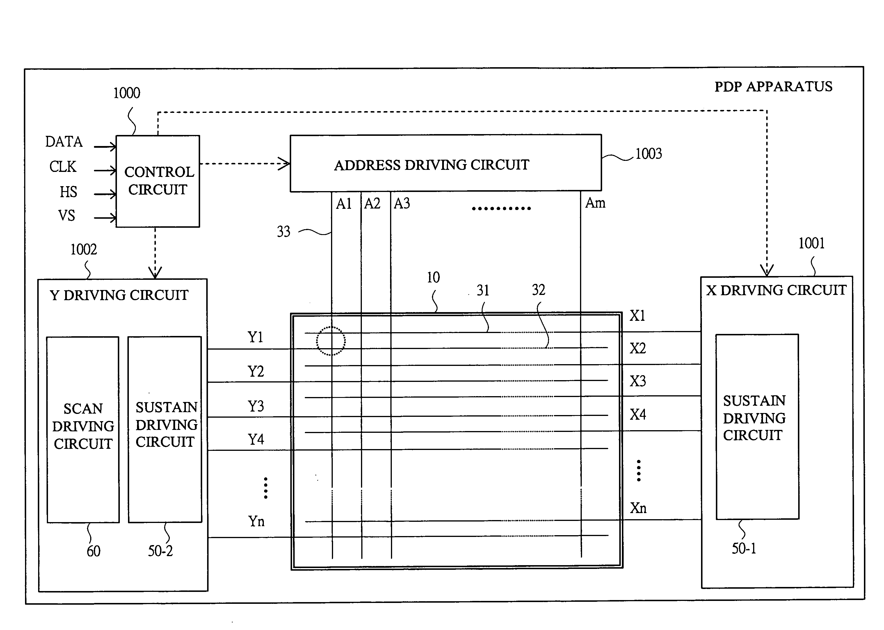
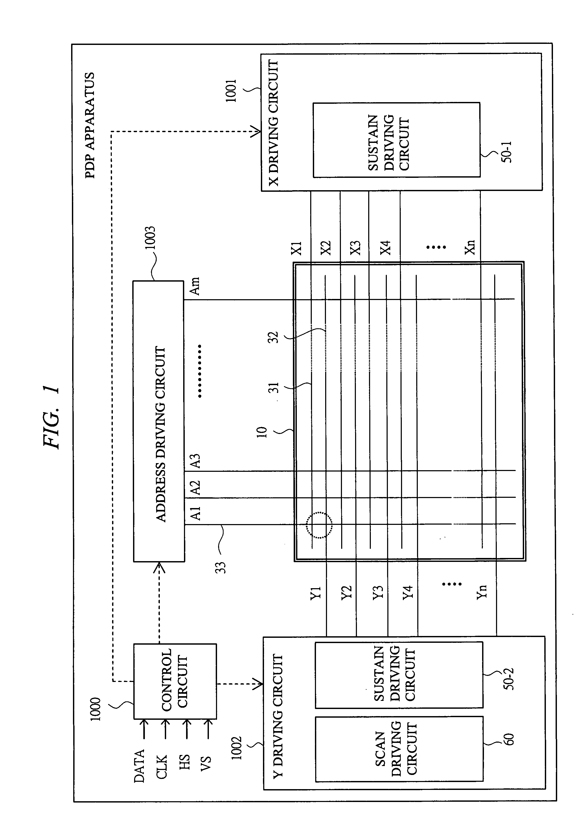
[0041]The first embodiment of the present invention will be described with reference to FIG. 1 to FIG. 3 and others. In the first embodiment, one coil (L0) is provided as a coil (L) for energy recovery of a sustain driving circuit. First, the basic structure of the PDP apparatus and the PDP common in the embodiments will be described.

[0042]

[0043]The entire structure of the PDP apparatus will be described with reference to FIG. 1. The PDP apparatus includes a PDP (panel) 10, a control circuit 1000, an X driving circuit 1001, a Y driving circuit 1002, and an address driving circuit 1003. The control circuit 1000 has a frame memory, a signal processing circuit and others. An image signal (DATA), a control clock (CLK), a horizontal synchronizing signal (HS), a vertical synchronizing signal (VS) and others are inputted to the control circuit 1000 to perform the process for the PDP driving control, and driving signals are outputted to each of the driving circuits and others. The X driving...

first structure example

[0053]Next, the structure of the driving circuit (first structure example of all embodiments) according to the first embodiment will be described with reference to FIG. 3 and others. In FIG. 3, the sustain driving circuit 50-1 has the energy recovery circuit 100 and the Vs clamp circuit 200, and it is connected to the X electrode 31 of the panel capacitor (C). Also, the sustain driving circuit 50-2 having the Vs clamp circuit 200-2 with the similar structure is connected to the Y electrode 32 of the panel capacitor (C). The sustain driving circuit is connected to each capacitor (C) corresponding to the display cell of the PDP 10.

[0054]In the Vs clamp circuit 200, a first power source (V1) 211 on a high-potential (v1) side and a second power source (V2) 212 on a low-potential (v2) side corresponding to the sustain discharge voltage (Vs) are connected, and as a switch (SC) for controlling the Vs clamp operation, a first switch (SCu) 221 and a second switch (SCd) 222 are provided. The ...

second embodiment

[0066]Next, the second embodiment of the present invention will be described with reference to FIG. 4 to FIG. 6 and others. In the second embodiment, two coils are independently provided as the coil (L) for energy recovery.

SECOND STRUCTURE EXAMPLE (2-1)

[0067]FIG. 4 shows the structure of the driving circuit according to the second embodiment (second structure example). In the sustain driving circuit 50-1, the Vs clamp circuit 200 has the same structure as described above.

[0068]In the energy recovery circuit 100, two independent coils, that is, a first coil (L1) 151 and a second coil (L2) 152 are provided as the coil (L) for energy recovery. The first coil (L1) 151 is used for the charging (charge supplying) operation to the capacitor (C), and the second coil (L2) 152 is used for the discharging (charge recovery) operation from the capacitor (C). In this example, these coils (L1, L2) have a relation in inductance (denoted by the same symbol) of L1≈L2.

[0069]Also, similar to that descr...


PUM


Abstract

In this PDP apparatus, in a sustain driving circuit device for supplying sustain discharge pulses, an energy recovery circuit has a coil, switches, and diodes, and a Vs clamp circuit has switches. In the energy recovery circuit, the switches are connected to a panel capacitor, and the coil is connected to a power source line with an intermediate potential of Vs, and a clamp diode and a power source connected thereto are connected to a node between the coil and the switch. As a control timing, at a timing of less than π / 2 of an LC resonance current cycle, the switch of the energy recovery circuit is turned OFF and then the switch of the Vs clamp circuit is turned ON, thereby performing the Vs clamp.

Description

CROSS-REFERENCE TO RELATED APPLICATION[0001]The present application claims priority from Japanese Patent Application No. JP 2007-078994 filed on Mar. 26, 2007, the content of which is hereby incorporated by reference into this application.TECHNICAL FIELD OF THE INVENTION[0002]The present invention relates to a plasma display apparatus (PDP apparatus) having a plasma display panel (PDP) and a driving circuit device thereof. More particularly, the present invention relates to a driving circuit for outputting sustain discharge pulses (sustain pulses).BACKGROUND OF THE INVENTION[0003]Conventionally, a driving circuit of PDP apparatus has a sustain discharge pulse driving circuit (abbreviated as sustain driving circuit) including an energy recovery circuit and a sustain discharge voltage (referred to as Vs) clamp circuit. The sustain driving circuit supplies sustain discharge pulses to the electrodes (display electrodes, that is, sustain (X) electrodes or scan (Y) electrodes) used for th...

Claims


Application Information

Patent Timeline
IPC IPC(8): G09G5/00G09G3/20G09G3/291G09G3/288G09G3/294G09G3/296G09G3/298
CPCG09G3/2965G09G2310/066G09G2330/021G09G3/296G09G3/294
Inventor SAKAMOTO, TETSUYAOTSUKA, AKIRATAKAGI, AKIHIROTOMIO, SHIGETOSHI
Owner HITACHI LTD
Why Eureka
Try Eureka