Voltage regulator

Active Publication Date: 2010-06-24
ABLIC INC
View PDF6 Cites 10 Cited by
  • Summary
  • Abstract
  • Description
  • Claims
  • Application Information

AI Technical Summary

Benefits of technology

[0010]The present invention has been made in view of the above-mentioned problem, and provides a voltage regulator capable of performing a stable circuit operation while improving undershoot characteristics thereof.
[0011]In order to solve the above-mentioned problem, the present invention provides a voltage regulator that operates so that an output voltage is kept constant, the voltage regulator including: an output transistor for outputting the output voltage; an undershoot improvement circuit that operates so that the output voltage increases, when an undershoot has occurred in the output voltage; and an output current limiting circuit for controlling, when an output current becomes an overcurrent, a control terminal voltage of the output transistor so that the output current is prevented from exceeding the overcurrent, and for disabling the undershoot improvement circuit.
[0012]According to the present invention, when the output current becomes an overcurrent, the output current limiting circuit disables the undershoot improvement circuit, and hence the undershoot improvement circuit does not cause the output voltage to increase, while the output current limiting circuit serving as a protection function allows the output voltage to decrease. Therefore, in case of overcurrent, the protection function provided for the voltage regulator is enabled, which results in the stable circuit operation of the voltage regulator.

Problems solved by technology

Therefore, there arises a problem that a circuit operation of the voltage regulator becomes unstable.

Method used


Image

  • Voltage regulator
  • Voltage regulator
  • Voltage regulator

Examples


Embodiment Construction

[0018]Now, referring to the accompanying drawings, an embodiment of the present invention is described.

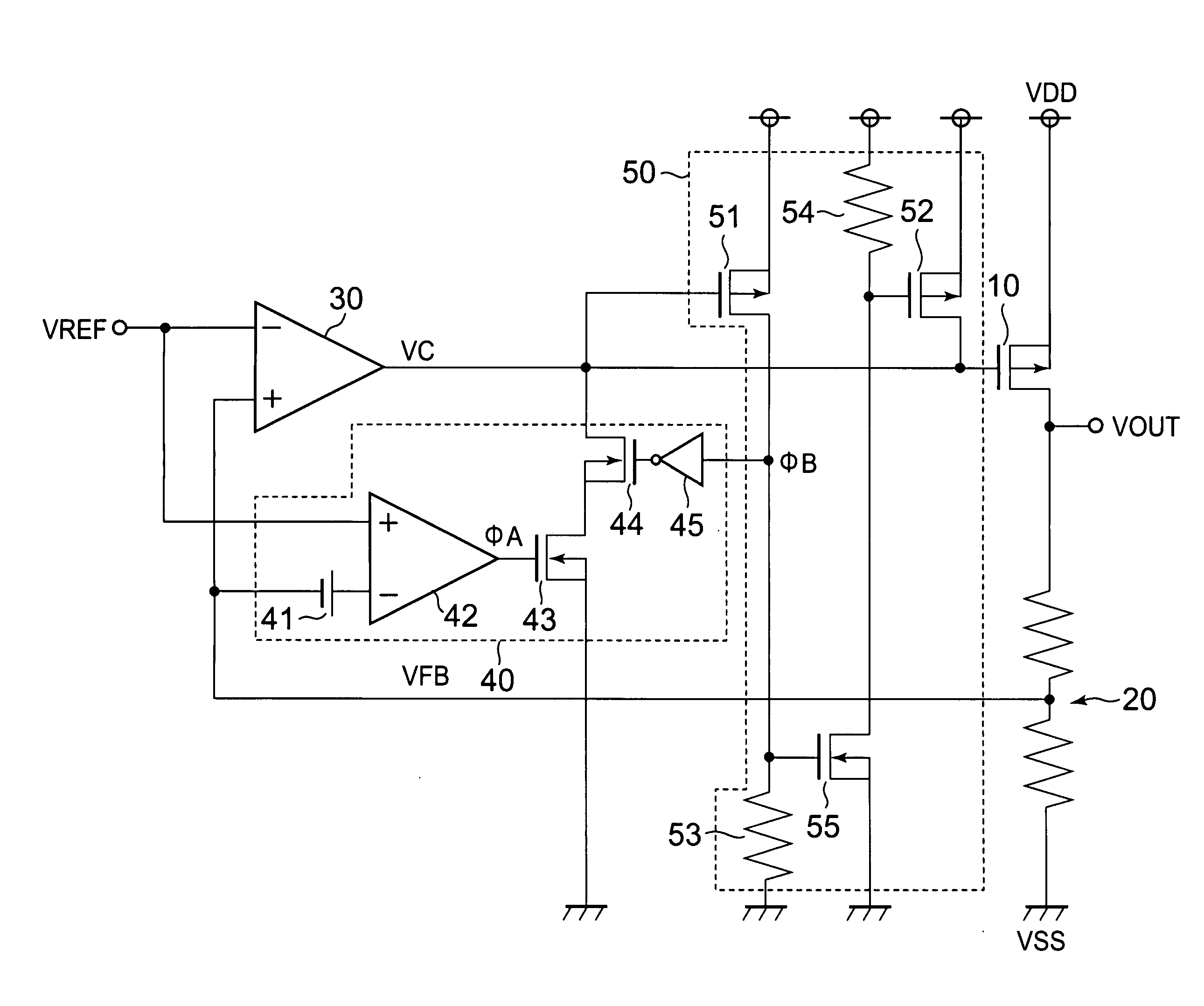
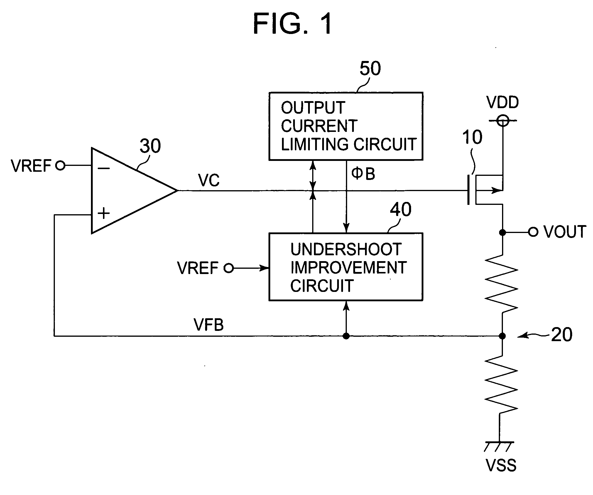
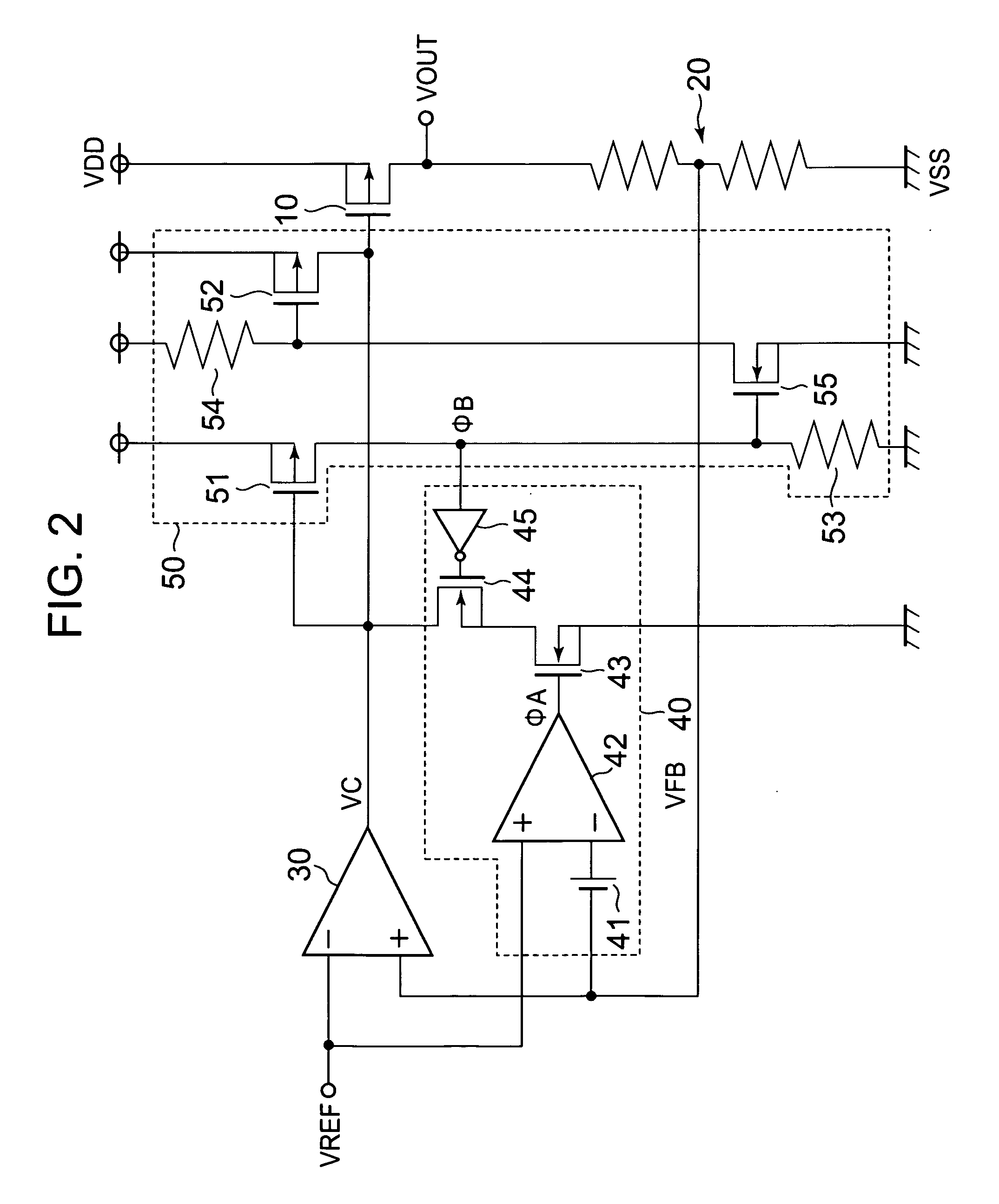
[0019]First, a configuration of a voltage regulator is described. FIG. 1 is a block diagram illustrating the voltage regulator of the present invention. FIG. 2 is a circuit diagram illustrating the voltage regulator of the present invention.

[0020]The voltage regulator includes an output transistor 10, a voltage divider circuit 20, an amplifier 30, an undershoot improvement circuit 40, and an output current limiting circuit 50.

[0021]The undershoot improvement circuit 40 includes an offset voltage generation circuit 41, a comparator 42, N-type metal oxide semiconductor (NMOS) transistors 43 and 44, and an inverter 45.

[0022]The output current limiting circuit 50 includes P-type metal oxide semiconductor (PMOS) transistors 51 and 52, resistors 53 and 54, and an NMOS transistor 55.

[0023]The output transistor 10 has a gate connected to an output terminal of the amplifier 30, a source con...


PUM


Abstract

Provided is a voltage regulator capable of performing a stable circuit operation while improving undershoot characteristics thereof. When an undershoot has occurred in an output voltage (VOUT), an undershoot improvement circuit (40) controls a control signal (VC) so that the output voltage (VOUT) may increase. When an output current becomes an overcurrent, an output current limiting circuit (50) controls the control signal (VC) so that the output current may be prevented from exceeding the overcurrent, and the output current limiting circuit (50) disables the undershoot improvement circuit (40).

Description

BACKGROUND OF THE INVENTION[0001]1. Field of the Invention[0002]The present invention relates to a voltage regulator that operates so that an output voltage may be kept constant.[0003]2. Description of the Related Art[0004]A conventional voltage regulator is described. FIG. 4 is a diagram illustrating the conventional voltage regulator.[0005]As an output voltage VOUT increases, a divided voltage VFB of a voltage divider circuit 92 also increases. On this occasion, an amplifier 94 compares the divided voltage VFB with a reference voltage VREF, and accordingly when the divided voltage VFB becomes higher than the reference voltage VREF, a control signal VC also increases. Then, an ON-state resistance of an output transistor 91 increases to decrease the output voltage VOUT. As a result, the output voltage VOUT is kept constant.[0006]On the other hand, as the output voltage VOUT decreases, the divided voltage VFB of the voltage divider circuit 92 also decreases. On this occasion, the amp...

Claims


Application Information

Patent Timeline
IPC IPC(8): G05F1/10
CPCG05F1/56
Inventor IMURA, TAKASHI
Owner ABLIC INC
Why Eureka
Try Eureka