Apparatus For Reproducing Signal From Multi-Layered Optical Disk
a multi-layer optical disk and apparatus technology, applied in the field of optical pickup apparatuses and optical disk apparatuses, can solve the problems of deterioration of the signal reproduced from a selected record layer, drop in and the s/n ratio of the reproduced signal may thus deteriorate, so as to achieve sufficient precision and satisfactory precision
- Summary
- Abstract
- Description
- Claims
- Application Information
AI Technical Summary
Benefits of technology
Problems solved by technology
Method used
Image
Examples
first embodiment
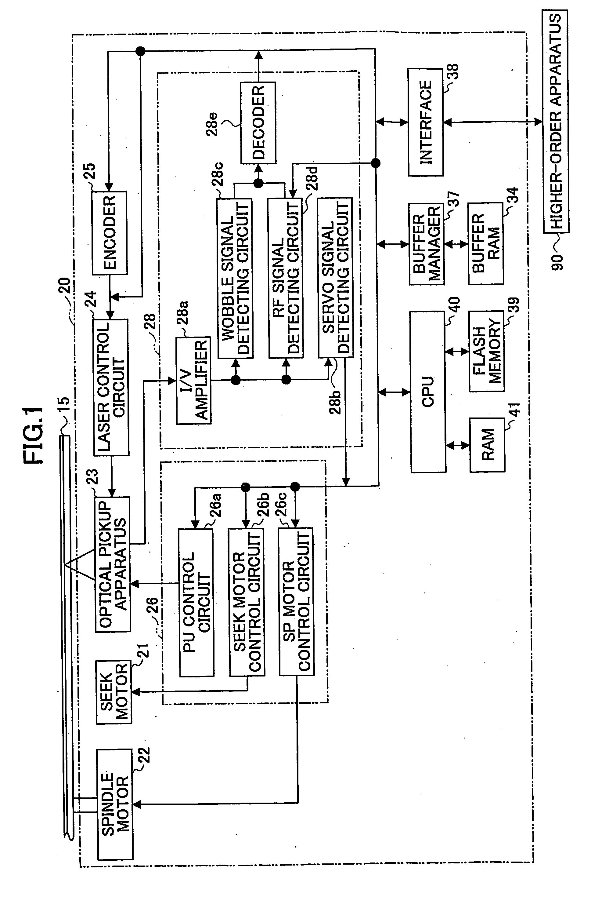
[0081]A first embodiment of the present invention will be described with reference to FIG. 1 through FIG. 10. FIG. 1 is a drawing showing a schematic configuration of an optical disc apparatus 20 according to the first embodiment.
[0082]The optical disc apparatus 20 shown in FIG. 1 includes a spindle motor 22 for revolving an optical disk 15, an optical pickup apparatus 23, a seek motor 21 for driving the optical pickup apparatus 23 in the sledge direction, a laser control circuit 24, an encoder 25, a servo control circuit 26, a reproduced signal processing circuit 28, a buffer RAM 34, a buffer manager 37, an interface 38, a flash memory 39, a CPU 40, and a RAM 41. Arrows shown in FIG. 1 only illustrates the flows of main signals and information items, and are not intended to represent all the connections between the blocks.
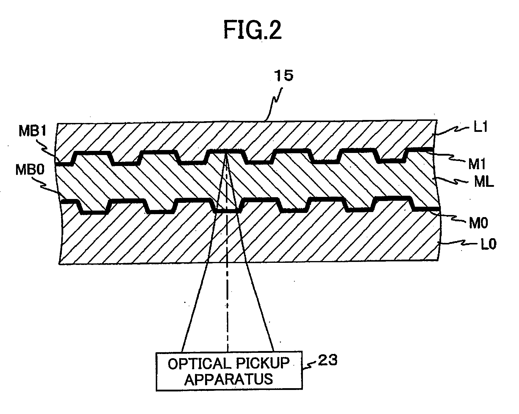
[0083]According to the first embodiment, the optical disc apparatus 20 is designed to conform to an optical disk having two recording layers, for example. That is...
second embodiment
[0130]In the following, a description will be given of a second embodiment of the present invention with reference to FIG. 1 through FIG. 14C.
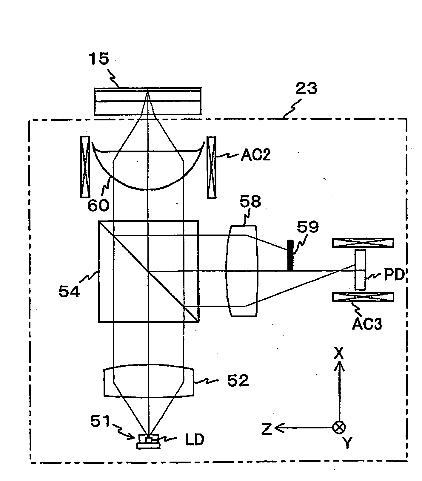
[0131]The second embodiment is a variation of the first embodiment. The second embodiment differs from the first embodiment in that, as shown in FIG. 11 serving as a non-limiting example, the photo detector PD is driven rather than driving the condenser lens 58 in the optical pickup apparatus 23. Namely, a photo detector actuator AC3, in place of the condenser lens actuator AC1, is provided as a means to drive the photo detector PD in the direction of the optical axis of the photo detecting surface. Consequently, as shown in FIG. 12 serving as a non-limiting example, the PU control circuit 26a includes a PDACT control circuit 267 for generating a signal (hereinafter referred to as a fourth drive signal for sake of convenience) for driving the photo detector actuator AC3. The PDACT control circuit 267 is provided in place of the condenser lens ...
third embodiment
[0141]In the following, a description will be given of a third embodiment with reference to FIG. 15 through FIG. 18B.
[0142]The third embodiment is a variation of the first embodiment. The third embodiment differs from the first embodiment in that a liquid crystal device pp serving as an opto-electrical device having its refractive index changing in response to an applied voltage is provided between the light blocking plate 59 and the photo detector PD in the optical pickup apparatus 23 as shown in FIG. 15 serving as a non-limiting example, and in that the condenser lens actuator AC1 is not provided. Consequently, as shown in FIG. 16 serving as a non-limiting example, the PU control circuit 26a includes a PP refractive index switching circuit 269 serving as a switching means for generating a voltage signal applied to the liquid crystal device PP. The PP refractive index switching circuit 269 is provided in place of the condenser lens ACT control circuit 265. Most other aspects of the...
PUM
 Abstract
Description
Claims
Application Information
 - R&D
- Intellectual Property
- Life Sciences
- Materials
- Tech Scout
- Unparalleled Data Quality
- Higher Quality Content
- 60% Fewer Hallucinations
Browse by: Latest US Patents, China's latest patents, Technical Efficacy Thesaurus, Application Domain, Technology Topic, Popular Technical Reports.
© 2025 PatSnap. All rights reserved.Legal|Privacy policy|Modern Slavery Act Transparency Statement|Sitemap|About US| Contact US: help@patsnap.com


