Beam stabilized fiber laser

a beam stabilized, fiber laser technology, applied in the direction of lasers, optical resonator shape and construction, manufacturing tools, etc., can solve the problems of insufficient solution for most precision applications, failure of laser operation or laser performance instability, and change in beam path, etc., to achieve the effect of increasing angular sensitivity

Active Publication Date: 2008-10-02
IMRA AMERICA
View PDF62 Cites 31 Cited by
  • Summary
  • Abstract
  • Description
  • Claims
  • Application Information

AI Technical Summary

Benefits of technology

[0013]No additional dedicated device for beam delivery stabilization between the laser head and the material to be processed can be a great benefit. Even if a position sensor is chosen to be located close to the material to be processed, the physical location of an active beam steering device in the laser head will be of advantage for increased angular sensitivity due to extended geometric distance.

Problems solved by technology

The most common cause of error is the change in the beam path due to a thermally induced opto-mechanical change in the properties of the material used.
For a laser cavity or an amplifier, this change can even result in failure of the laser operation or instability in laser performance.
A passive method can be adopted by carefully choosing the optics and opto-mechanical materials, but this will not be a sufficient solution for most precision applications.
Such a method often requires expensive and time-consuming maintenance and is not applicable for many laser application systems.
Indeed, the extreme sensitivity of thermo-optical stability of solid-state lasers has been recognized as a major barrier to the acceptance of short or ultrashort pulse lasers by industry.
The parameter for the active beam control is the laser head performance such as the output power, but the geometric beam path out of the laser head cannot be controlled.

Method used


Image

  • Beam stabilized fiber laser
  • Beam stabilized fiber laser
  • Beam stabilized fiber laser

Examples


Embodiment Construction

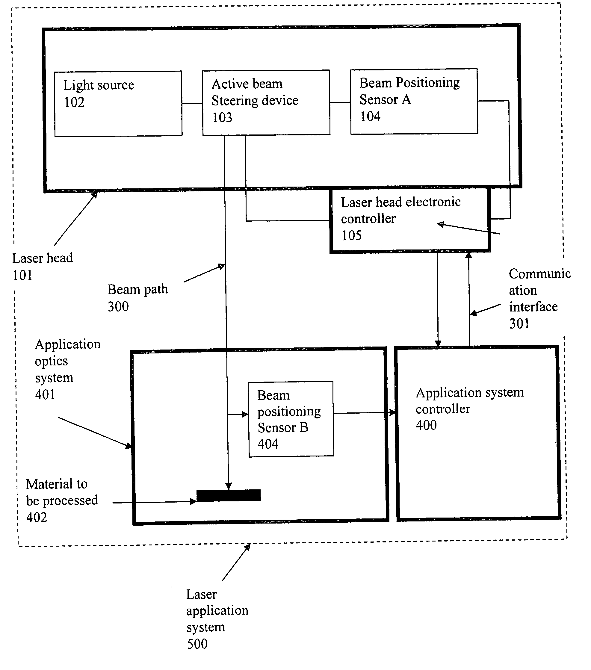
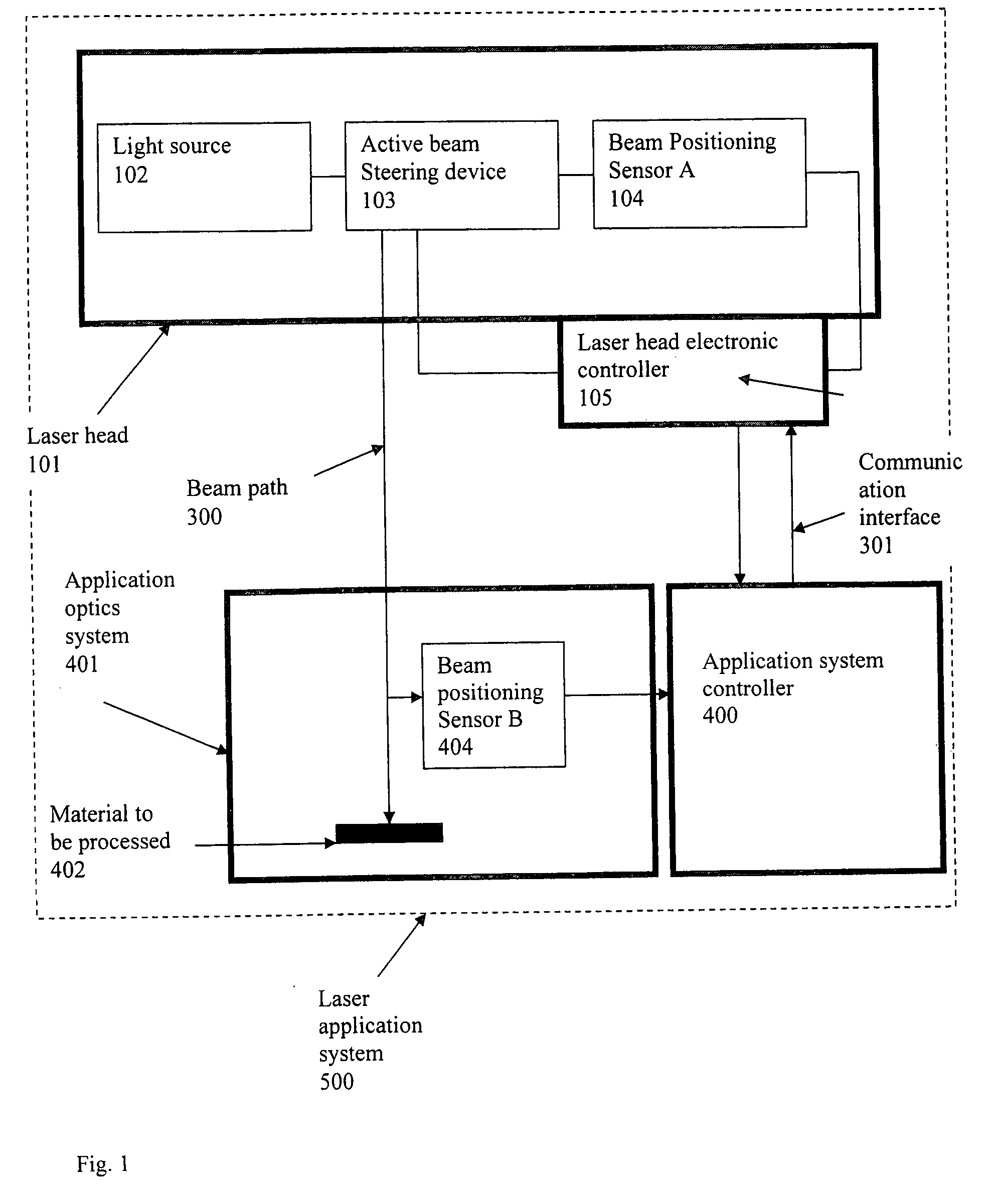
[0028]In general a laser application system comprises a laser head, laser head controller, delivery optics delivering the beam to the material to be processed and control electronics of the application system. The laser head and system electronics are linked with an interface protocol. Any active devices contained in the laser head and its electronics are desired to be controlled by the system electronics. The beam path control from the laser head to the material to be processed is actively controlled via devices incorporated into the laser head.

[0029]The parameters determining the beam path to the application system are the beam angle and the amount of beam shift. The combination of a beam steering device and position-sensitive can basically provide the degree of freedom for the control. Three major functional parts are required thereby: a beam positioning sensor, the active beam steering device and an electronic feedback loop.

[0030]The basic method is to measure i) the beam positi...


PUM

PropertyMeasurementUnit
diameteraaaaaaaaaa
diameteraaaaaaaaaa
angleaaaaaaaaaa

Abstract

A laser head generating ultrashort pulses is integrated with an active beam steering device in the head. Direct linkage with an application system by means of an adequate interface protocol enables the active device to be controlled directly by the application system.

Description

[0001]This Application is Related to Provisional Application No. 60 / 578,875 filed Jun. 14, 2004; the disclosure of which is incorporated herein by reference.BACKGROUND OF THE INVENTION[0002]1. Field of the Invention[0003]The present invention is related to a method for stabilization of the geometric optical beam path of a laser head for the application of precision laser material processing.[0004]2. Description of the Related Art[0005]Controlling the beam path out of a light source is crucial for an optical system. A precision laser processing system requires a precise guidance of the laser beam from the laser head to the target material to be processed. The accuracy will usually determine the precision of the processing. The most common cause of error is the change in the beam path due to a thermally induced opto-mechanical change in the properties of the material used. For a laser cavity or an amplifier, this change can even result in failure of the laser operation or instability ...

Claims


Application Information

Patent Timeline
Patent Type & Authority Applications(United States)
IPC IPC(8): H01S3/00
CPCH01S3/0057H01S3/0071H01S3/067H01S3/2308B23K26/043
Inventor CHO, GYU C.BOUEVITCH, OLEG
Owner IMRA AMERICA
Why Eureka
Try Eureka