Method for X-ray wavelength measurement and X-ray wavelength measurement apparatus
a wavelength measurement and wavelength measurement technology, applied in the direction of instruments, material analysis using wave/particle radiation, nuclear engineering, etc., can solve the problems of complex structure and inability to simply measure, and achieve the effect of simple alignment, high precision and easy measuremen
- Summary
- Abstract
- Description
- Claims
- Application Information
AI Technical Summary
Benefits of technology
Problems solved by technology
Method used
Image
Examples
embodiment 1
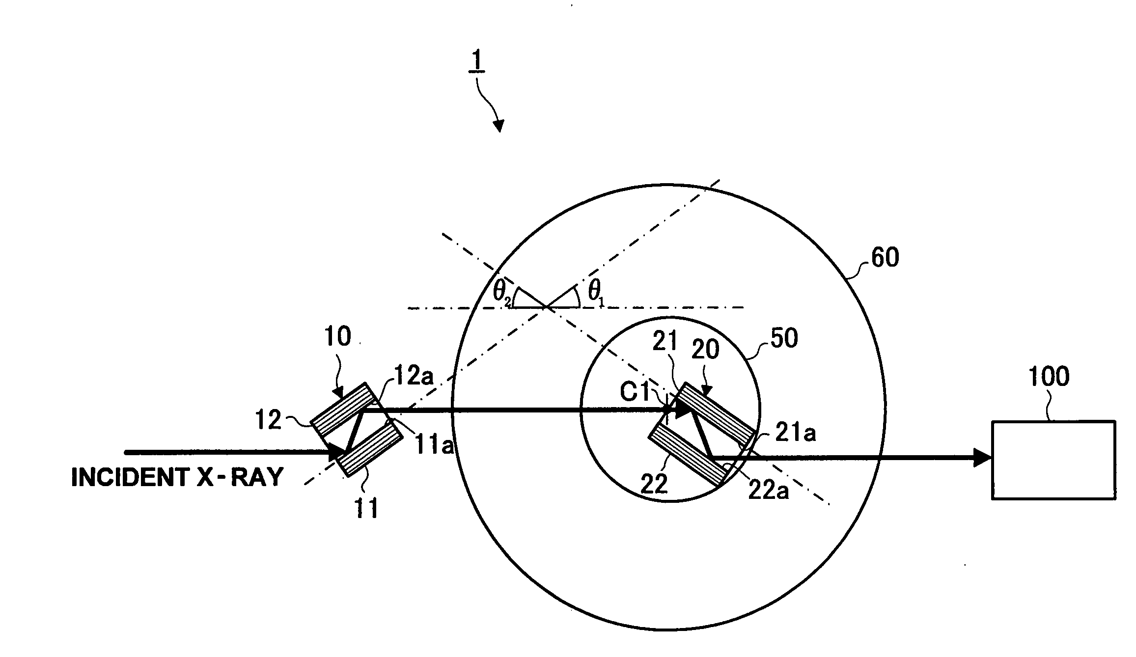
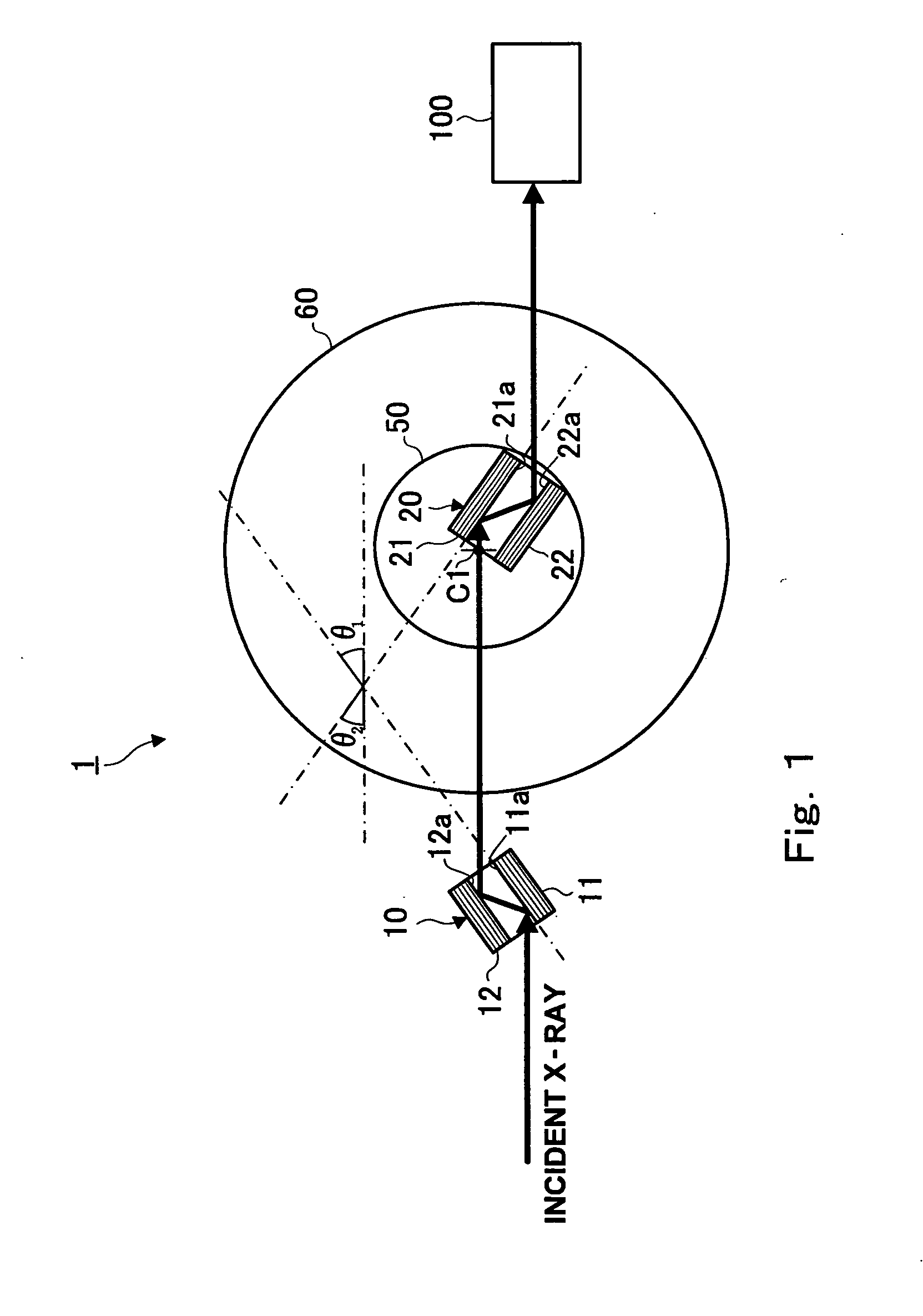
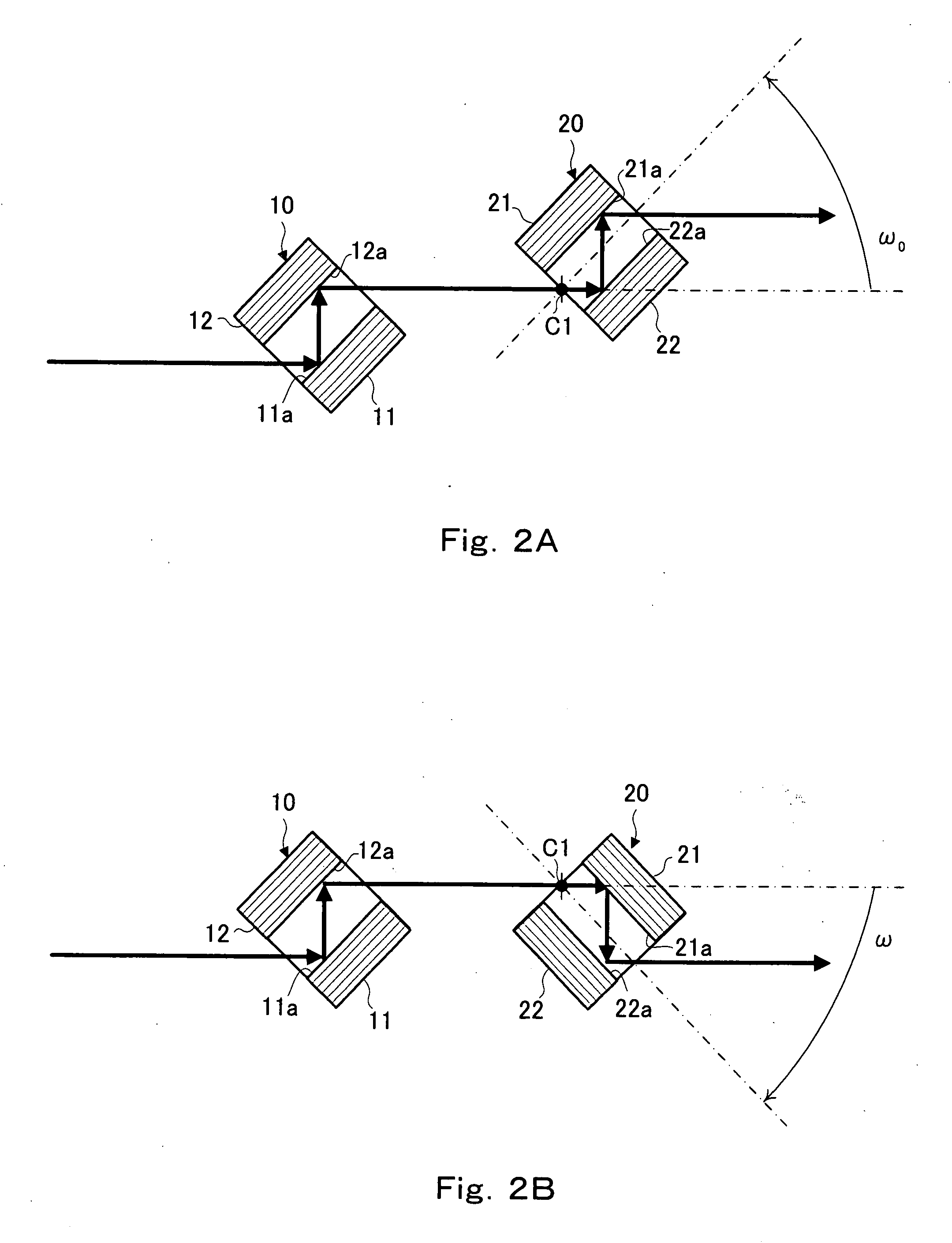
[0037]FIG. 1 is a plan view showing the outline of the configuration of an X-ray wavelength measurement apparatus 1 according to the present invention. As shown in FIG. 1, the X-ray wavelength measurement apparatus 1 includes a channel-cut crystal for collimator 10, a channel-cut crystal for wavelength measurement 20, a rotatable platform 50, an angle detector 60 and an X-ray detector 100. The channel-cut crystal is prepared by carving grooves to a unitary crystal block, and the parallel walls on both sides thereof are utilized for reflection, that is, diffraction. For the channel-cut crystal, the whole is composed of unitary crystal, and therefore all X-rays Bragg-reflected by one crystal wall cause Bragg reflection by the other crystal wall. The X-ray wavelength measurement apparatus 1 spectrally reflects X-ray having a specified wavelength out of incident X-ray having a continuous spectrum, and measures the intensity thereof with the X-ray detector 100. The X-ray wavelength measu...
embodiment 2
[0054]In the above-described Embodiment 1, the rotation center C1 is so provided that X-ray enters different cut planes when the channel-cut crystal for wavelength measurement 20 is set to respective arrangements of (+, −) and (−, +), but the rotation center may be provided so that X-ray may enter the identical cut plane. FIG. 3 is a schematic drawing showing the X-ray wavelength measurement apparatus 1 in which the channel-cut crystal for wavelength measurement is so arranged that X-ray enters the identical cut plane. A channel-cut crystal for collimator 30 has a first crystal wall 31 and a second crystal wall 32, and, at respective crystal walls, a first cut plane 31a and a second cut plane 32a facing each other are formed. The lengths of respective crystal walls are shortened in different directions in accordance with the passing channels of X-ray beams so that a large diffraction angle can be obtained. For a scheme to obtain a large diffraction angle, as shown in FIG. 4, crystal...
embodiment 3
[0062]The above-described X-ray wavelength measurement apparatus 1 of the Embodiment 1 can measure absolute wavelength with high precision, but it is also possible to carry out precise calibration by giving additional self-calibration function to the angle detector.
[0063]FIG. 6 is a side view showing an X-ray wavelength measurement apparatus 2 provided with an angle detector having self-calibration function. As shown in FIG. 6, the X-ray wavelength measurement apparatus 2 includes a channel-cut crystal for collimator 10, a channel-cut crystal for wavelength measurement 20, a fixed platform 49, a rotatable platform 50, a rotary driving instrument 55, an angle detector 60, a controlling section 70 and a detector 100. The rotary driving instrument 55, the angle detector 60 and the controlling section 70 constitute a rotation control mechanism.
[0064]The rotatable platform 50 is connected to the rotary driving instrument 55 capable of rotation at intervals of a minute angle. The rotary d...
PUM
 Abstract
Description
Claims
Application Information
 - R&D
- Intellectual Property
- Life Sciences
- Materials
- Tech Scout
- Unparalleled Data Quality
- Higher Quality Content
- 60% Fewer Hallucinations
Browse by: Latest US Patents, China's latest patents, Technical Efficacy Thesaurus, Application Domain, Technology Topic, Popular Technical Reports.
© 2025 PatSnap. All rights reserved.Legal|Privacy policy|Modern Slavery Act Transparency Statement|Sitemap|About US| Contact US: help@patsnap.com


