Device For and Method of Generating a Virbration Source-Driving-Signal

Active Publication Date: 2008-10-02
MMD HONG KONG HLDG LTD
View PDF7 Cites 23 Cited by
  • Summary
  • Abstract
  • Description
  • Claims
  • Application Information

AI Technical Summary

Benefits of technology

[0009]It is an object of the invention to enhanc

Problems solved by technology

However, in many cases, the low-frequency part of the audio signal is not suitable for generating vibrati

Method used


Image

  • Device For and Method of Generating a Virbration Source-Driving-Signal
  • Device For and Method of Generating a Virbration Source-Driving-Signal
  • Device For and Method of Generating a Virbration Source-Driving-Signal

Examples


Embodiment Construction

[0041]The illustrations in the drawings are schematic. In different drawings, similar or identical elements are denoted by the same reference signs.

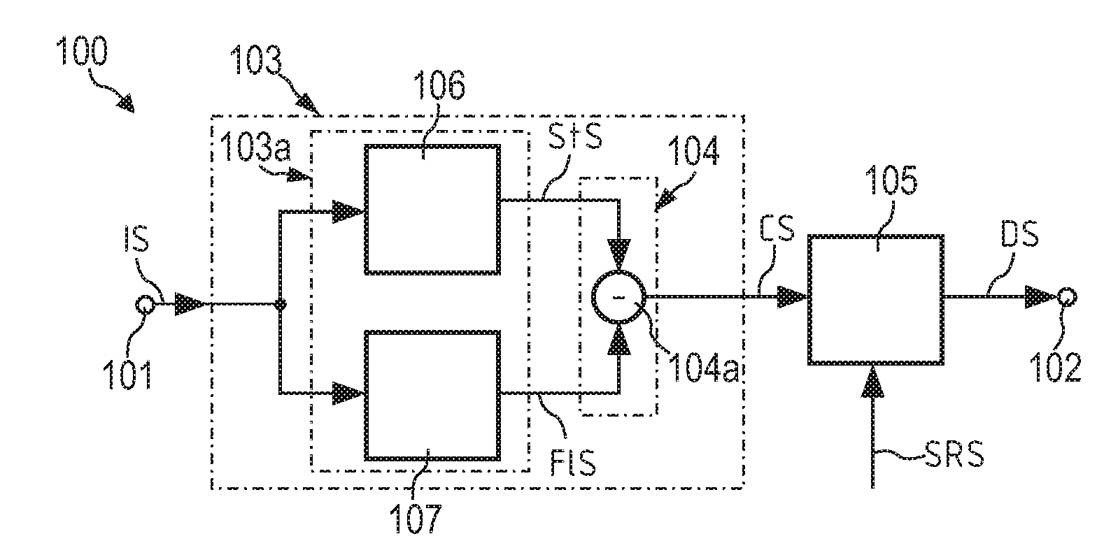
[0042]A device 100 for generating a vibration source-driving signal in accordance with an embodiment of the invention will now be described with reference to FIG. 1.

[0043]The device 100 for generating a vibration source driving signal DS comprises an input 101 for receiving an input signal IS and an output 102 for supplying said driving signal DS, generating means 103 adapted to generate a control signal CS which is representative of dynamic signal changes of the input signal IS, and a processing unit 105 adapted to process a source signal SRS based on the control signal CS yielding said driving signal DS.

[0044]In the present case, the generating means 103 comprises an extraction unit 103a adapted to extract or generate a stationary signal StS and a fluctuating signal FlS from the input signal IS, and combining means 104 for generating t...


PUM


Abstract

A device (100) for generating a vibration source driving signal (DS) is described, which device (100) comprises an input (101) for receiving an input signal (IS) and an output (102) for providing said driving signal (DS), generating means (103; 803) for generating a control signal (CS) which is representative of dynamic signal changes of the input signal (IS), and a processing unit (105; 201; 301; 401; 804) adapted to process a source signal (SRS; IAS) based on the control signal (CS) yielding said driving signal (DS).

Description

FIELD OF THE INVENTION[0001]The invention relates to a device for generating a vibration source-driving signal.[0002]The invention further relates to a method of generating a vibration source-driving signal.[0003]The invention also relates to a program element.[0004]Furthermore, the invention relates to a computer-readable medium.BACKGROUND OF THE INVENTION[0005]In the field of consumer electronics, devices with a vibration source or an internal vibration unit are becoming more and more important. Particularly, an increasing number of users are interested in vibration headphones or gaming headphones, i.e. headphone devices with internal vibration units aimed at providing gaming enthusiasts with an immersive sound experience that will dynamically add to the excitement and enjoyment of the latest action-packed computer, console and portable games.[0006]Such a gaming headphone has been introduced on the market by the applicant and is known, for instance, by the model name of “SHG8100”....

Claims


Application Information

Patent Timeline
IPC IPC(8): H04R3/04H04R3/14
CPCH04R3/14H04R3/04
Inventor TANGHE, LOIC BERNARDLU, FENGWAGENAARS, WILHELMUS MARIA
Owner MMD HONG KONG HLDG LTD
Why Eureka
Try Eureka