Sliding element procedure and device for its production

a technology of sliding elements and sliding plates, applied in the field of sliding elements, can solve the problems of high cost of production of such sliding elements, low production efficiency, and low cost of sliding elements, and achieve the effect of low cost and low cos

Inactive Publication Date: 2008-10-02
FEDERAL MOGUL DEVA
View PDF16 Cites 7 Cited by
  • Summary
  • Abstract
  • Description
  • Claims
  • Application Information

AI Technical Summary

Benefits of technology

[0010]The object of this invention is to provide a low cost, efficient method for producing such a sliding element, A further object is to provide a d...

Problems solved by technology

Because of the many individual, in some cases manual operating steps, from the plastic thread to the finished sliding element, relatively long non-productive times are experienced.
The production of such sliding elements is expensive.
The winding ...

Method used


Image

  • Sliding element procedure and device for its production
  • Sliding element procedure and device for its production
  • Sliding element procedure and device for its production

Examples


Embodiment Construction

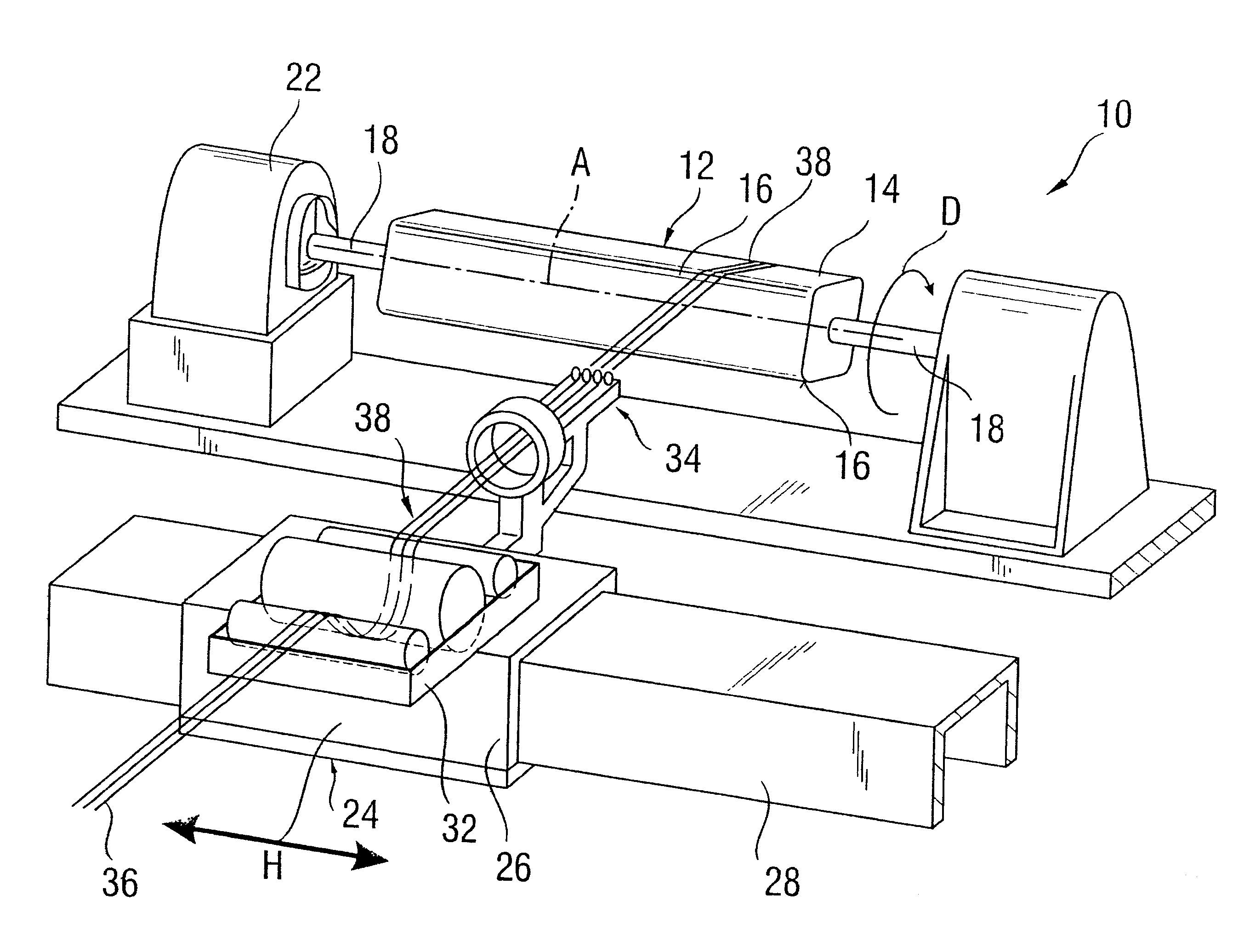
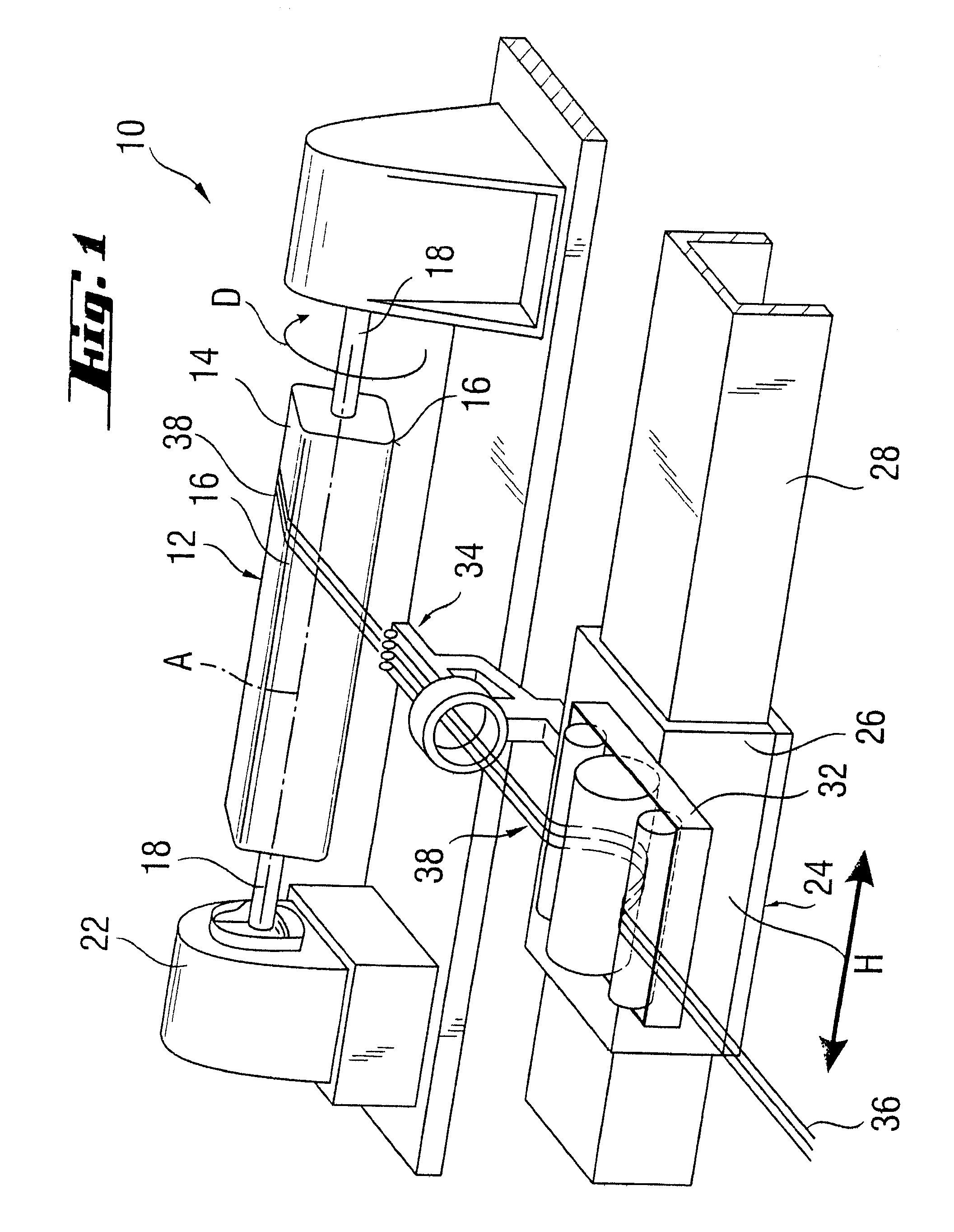
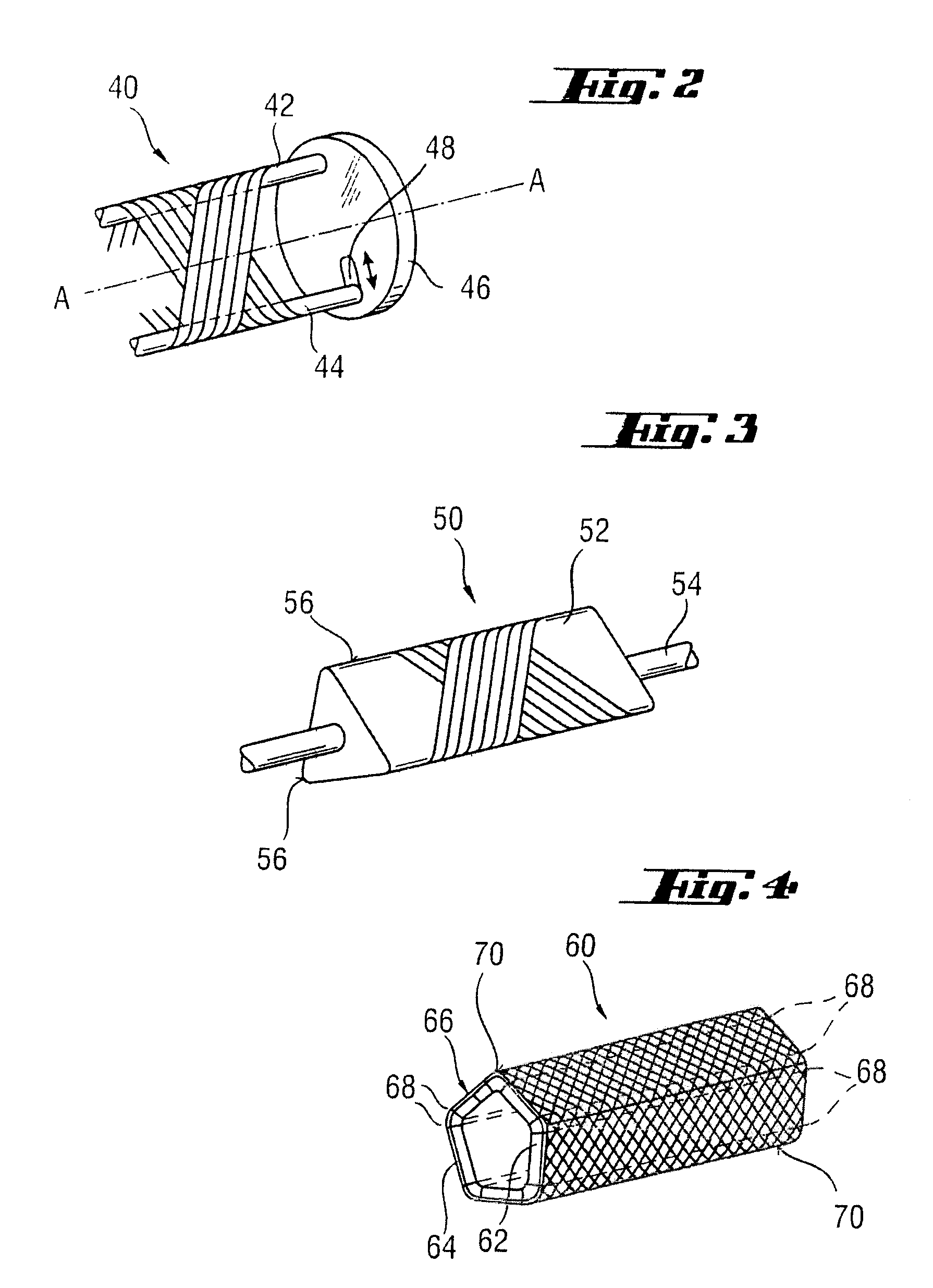
[0045]The exemplary embodiment of winding device 10 according to the invention, shown in FIG. 1, has a winding core 12 mounted rotatably about its longitudinal axis A, in the form of a square tube or mandrel 14, with rounded edges 16. Rounded edges 16 reduce the mechanical loading of the thread during winding and hence the risk that it might tear. Square tube 14 is mounted rotatably on both sides by means of a shaft 18 and is rotarily displaced by a drive 22.

[0046]Winding device 10 also has a guide 24 that can be moved back and forth along longitudinal axis A. This guide is formed by a carriage 26, which is moved back and forth by means of linear drive on a rail 28, which is aligned parallel with longitudinal axis A. Carriage 26 has an impregnating tank 32 filled with synthetic resin and guiding elements 34 for feeding a thread bundle 38 consisting of a plurality of threads 36.

[0047]Because of rotary movement D of winding core 12 on the one hand and back and forth movement H of guid...


PUM

PropertyMeasurementUnit
Radiusaaaaaaaaaa
Plasticityaaaaaaaaaa

Abstract

A method and a device is provided for producing a flat or arc-shaped sliding element with a very large radius of curvature. The sliding element has a sliding layer based on a fiber reinforced plastic with a plastic matrix and a reinforcing element containing at least one thread. The reinforcing element is deposited on a polygonal winding core by means of a guide with the addition of a synthetic resin forming the plastic matrix. The flat or arc-shaped segments formed between the edges are separated from the tubular, polygonal winding body thus formed after it has set.

Description

RELATED APPLICATIONS[0001]This application claims priority to German Patent Application 10 2006 043 065.4-43, filed Sep. 14, 2006 and German Patent Application 10 2006 042 999.0-43, filed Sep. 14, 2006.BACKGROUND OF THE INVENTION[0002]1. Technical Field[0003]The invention relates to a sliding element, in particular a flat or bent sliding element with a very large radius of curvature, which has at least one sliding layer based on fiber-reinforced plastic with a plastic matrix and a reinforcing element containing at least one fiber or thread, a method and a device for its production.[0004]2. Related Art[0005]The use of composite fiber materials for sliding bearings, particularly on the basis of epoxy resins, is of prior art. Such sliding bearings consist, as is well known, of a single-layer sliding layer material or of a bearing material constructed from two layers, a support layer and a sliding layer. A support layer is typically characterised by a glass fiber or carbon fiber reinfor...

Claims


Application Information

Patent Timeline
IPC IPC(8): C08J5/16F16C33/20B32B5/00B21D53/10
CPCB29C53/562Y10T29/49679B29C53/8066B29C53/821B29C69/002B29C70/025B29C70/32B29C2793/009B29K2027/18B29K2067/00F16C17/02F16C29/02F16C33/201F16C33/208Y10T29/53104Y10T29/4967B29C53/665F16C2208/86F16C2220/28
Inventor LAAL RIAHI, KAMRANLINKER, ARMINROOS, UDO
Owner FEDERAL MOGUL DEVA
Why Eureka
Try Eureka