Ceramic Thermal Barrier Coating

a thermal barrier and ceramic technology, applied in the field of materials technology, can solve the problems of high cost, disadvantage of this method, and high cost, and achieve the effects of reducing the cost of thermal barrier coating, high cost, and high cos

Inactive Publication Date: 2008-10-02
GENERAL ELECTRIC TECH GMBH
View PDF7 Cites 8 Cited by
  • Summary
  • Abstract
  • Description
  • Claims
  • Application Information

AI Technical Summary

Benefits of technology

[0018]It is advantageous for the volume fraction of the intermetallic compound in the coating to be approximately 80% on the surface of the component and approximately 5% on the free surface.

Problems solved by technology

The high costs, however, are a disadvantage of this method.
Disadvantageously, this is, on the one hand, very expensive and, on the other hand, often not practically feasible.
This does not, however, have a positive effect on the stress gradients and therefore on reducing the flaking risk of the TBC.

Method used


Image

  • Ceramic Thermal Barrier Coating
  • Ceramic Thermal Barrier Coating
  • Ceramic Thermal Barrier Coating

Examples


Embodiment Construction

[0024]The invention will be explained in more detail below with the aid of an exemplary embodiment.

[0025]Coatings and methods embodying principles of the present invention may be employed for all components which are exposed to high temperatures and oxidative / corrosive environmental effects, for example blades, hot-spot segments, or parts of the combustion chambers of gas turbines.

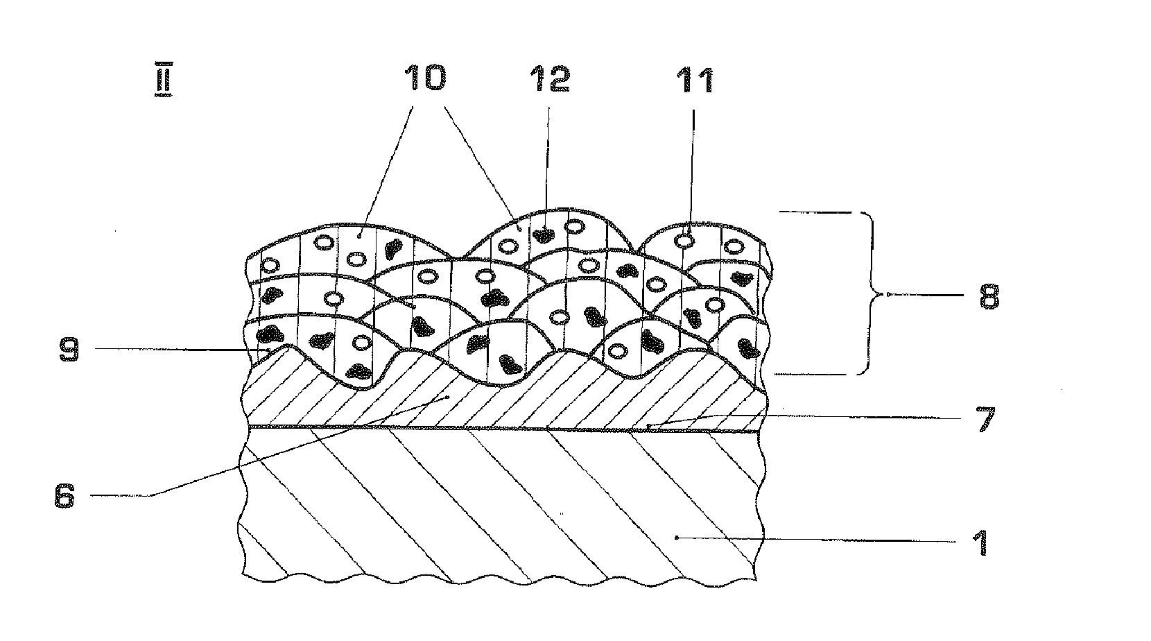
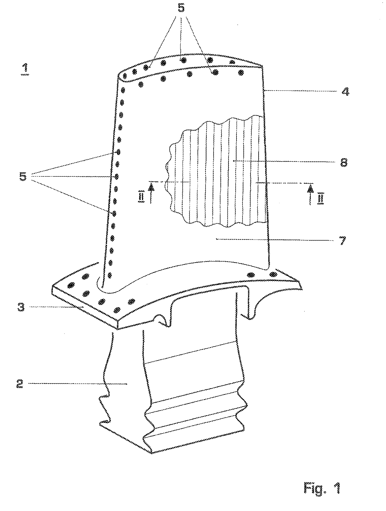
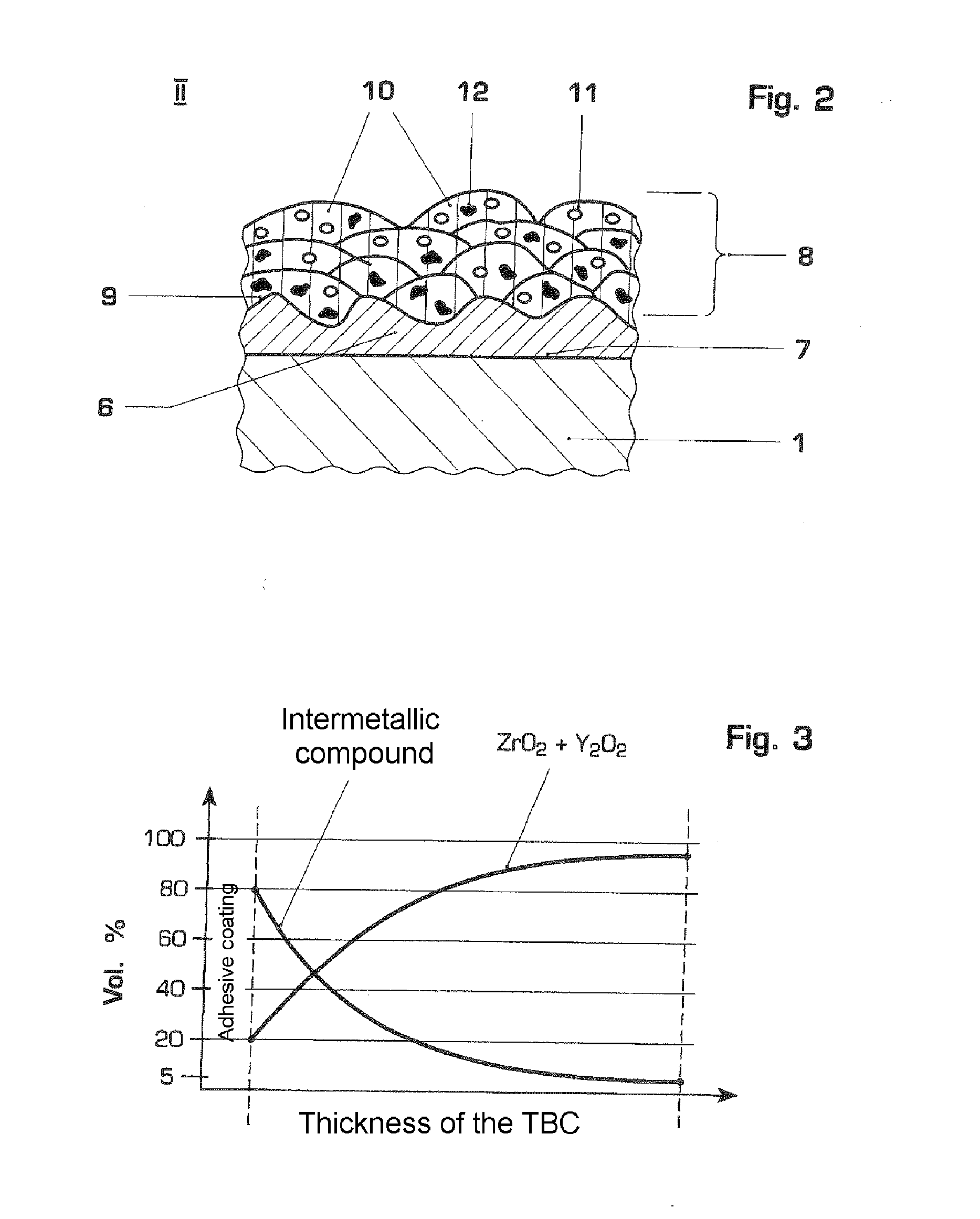
[0026]FIG. 1 shows a rotor blade of a gas turbine in perspective representation as an example of such components 1. The rotor blade 1 includes a blade root 2, a platform 3, and a blade body 4 which contains cooling air channels, the openings of which are denoted by 5 in FIG. 1. The rotor blade 1 is anchored by its blade root 2 into circumferential grooves in the rotor (not shown) of the gas turbine. During operation of the turbine, the blade body 4 is exposed to hot combustion gases so that the surface 7 of the blade body 4 is subjected both to the hot combustion gases and to attacks by oxidation, corrosio...


PUM

PropertyMeasurementUnit
volume fractionaaaaaaaaaa
thicknessesaaaaaaaaaa

Abstract

A ceramic thermal barrier coating (8) for coating the surface (7) of a component (1) of a nickel-based superalloy, and an adhesive coating optionally applied thereon (6), preferably a gas turbine component, includes zirconium oxide (ZrO2) stabilized by yttrium oxide (Y2O3) and production-related impurities, as well as at least one high-temperature and oxidation resistant intermetallic compound, for example NiAl, YRh, ErIr, the volume fraction of which decreases continuously or in stages as the distance from the surface (7) of the component (1)/the adhesive coating (6) increases. Advantageously, a less steep stress gradient is produced by gradually varying the composition of the thermal barrier coating (8). This leads to an increased expansion tolerance of the thermal barrier coating (8) and thus, on the one hand, to an increased lifetime under thermal loading (no flaking) and, on the other hand, the possibility of applying thicker thermal barrier coatings (8), and therefore of using the coated components (1) at higher temperatures.

Description

[0001]This application is a Continuation of, and claims priority under 35 U.S.C. § 120 to, International application number PCT / EP2006 / 063826, filed 4 Jul. 2006, and claims priority therethrough under 35 U.S.C. § 119 to Swiss application number 01152 / 05, filed 12 Jul. 2005, the entireties of which are incorporated by reference herein.BACKGROUND[0002]1. Field of Endeavour[0003]The invention concerns the field of materials technology. It relates to a ceramic thermal barrier coating which is used to coat heavily thermally loaded components, for example rotor blades of a gas turbine.[0004]2. Brief Discussion of Related Art[0005]In order to increase the efficiency of gas turbines, they are run at very high operating temperatures. The components exposed to the hot gases, for example guide vanes and rotor blades or combustion chamber elements, are therefore provided in a known way with thermal barrier coatings (TBC) on their surface in order to achieve higher operating temperatures and / or ...

Claims


Application Information

Patent Timeline
Patent Type & Authority Applications(United States)
IPC IPC(8): B32B15/04B05D1/36
CPCC23C4/02C23C4/04C23C30/00F01D5/288C23C28/3215C23C28/36C23C28/321C23C28/345C23C28/3455
Inventor NAZMY, MOHAMED YOUSSEF
Owner GENERAL ELECTRIC TECH GMBH
Why Eureka
Try Eureka