
Self-Crimping Radiopaque marker

a radiopaque marker and self-crimping technology, applied in medical preparations, medical science, surgery, etc., can solve the problem that the radiopaque of nickel-titanium alloys is not enough to be used as suitable marker bands in applications

Inactive Publication Date: 2008-10-02
MEDTRONIC VASCULAR INC
View PDF12 Cites 16 Cited by
  • Summary
  • Abstract
  • Description
  • Claims
  • Application Information

AI Technical Summary

Benefits of technology

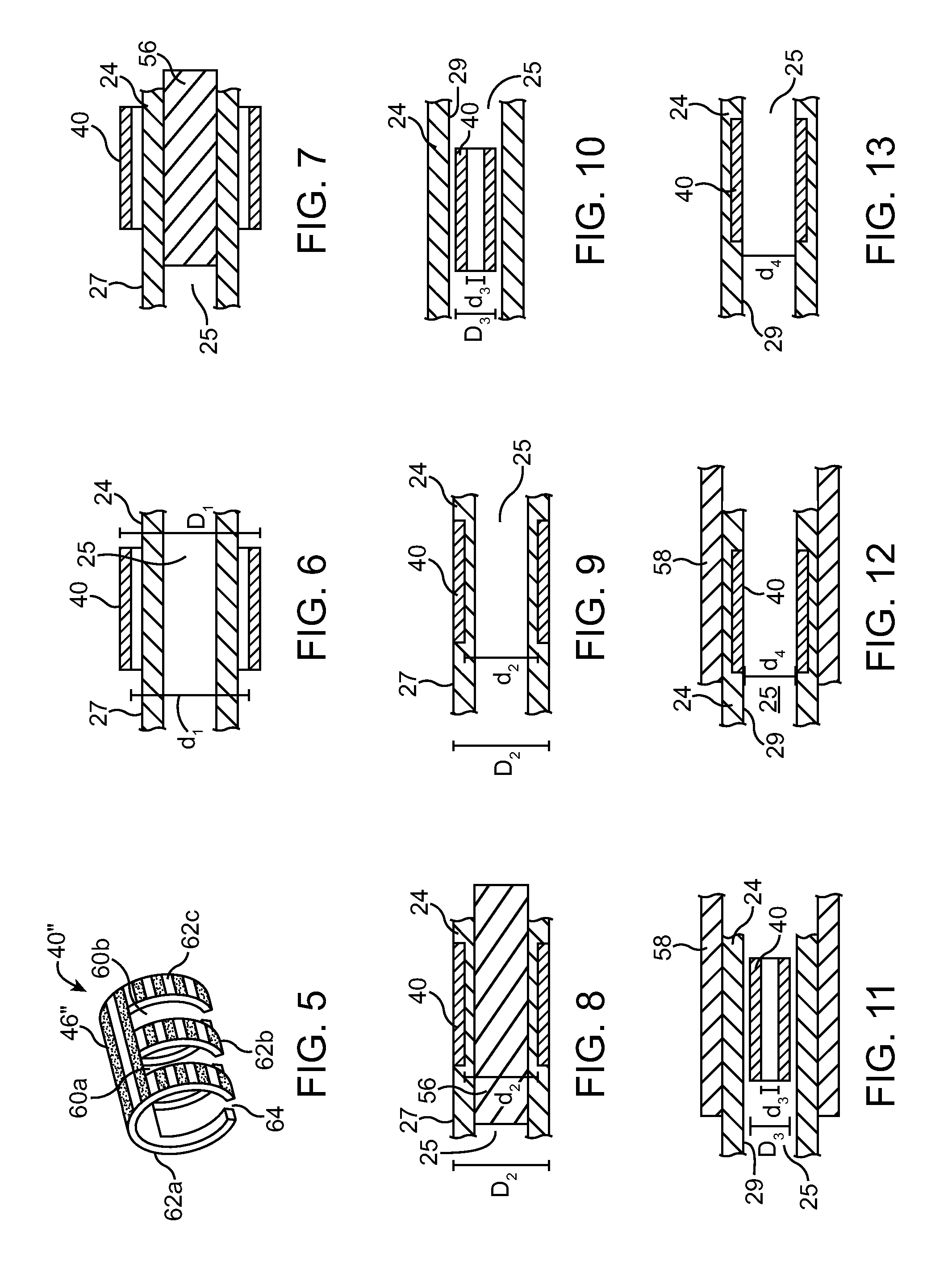
[0007]Alternatively, the original configuration of the marker band has an inner diameter that is approximately equal to the inner diameter of the tubular member. At a first temperature, the marker band is deformed to a deformed configuration in which an outer diameter of the marker band is smaller than the inner diameter of the tubular member and the marker band is placed inside the lumen of the tubular member. The temperature of the shape-memory material of the marker band is increased to a second temperature such that the marker band returns to its original configuration, thereby expanding the marker band to secure it to the inner surface of the tubular member.

Problems solved by technology

U.S. Pat. No. 5,485,667 describes a marker band made of a shape-memory material such as a nickel-titanium alloy, however, nickel-titanium alloys are not sufficiently radiopaque to be used as suitable marker bands in applications where the marker band must have a small thickness, such as in coronary applications.

Method used


Image

  • Self-Crimping Radiopaque marker
  • Self-Crimping Radiopaque marker
  • Self-Crimping Radiopaque marker

Examples


Embodiment Construction

[0022]Specific embodiments of the present invention are now described with reference to the figures, where like reference numbers indicate identical or functionally similar elements.

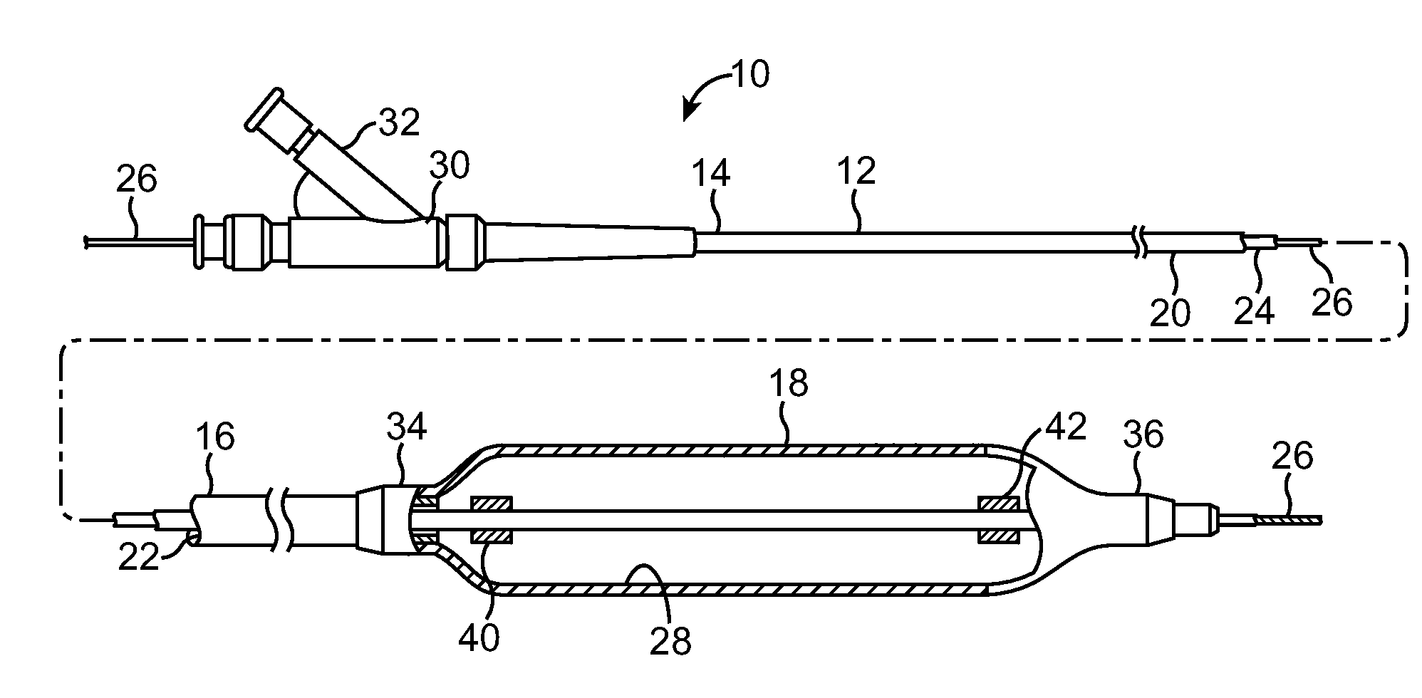
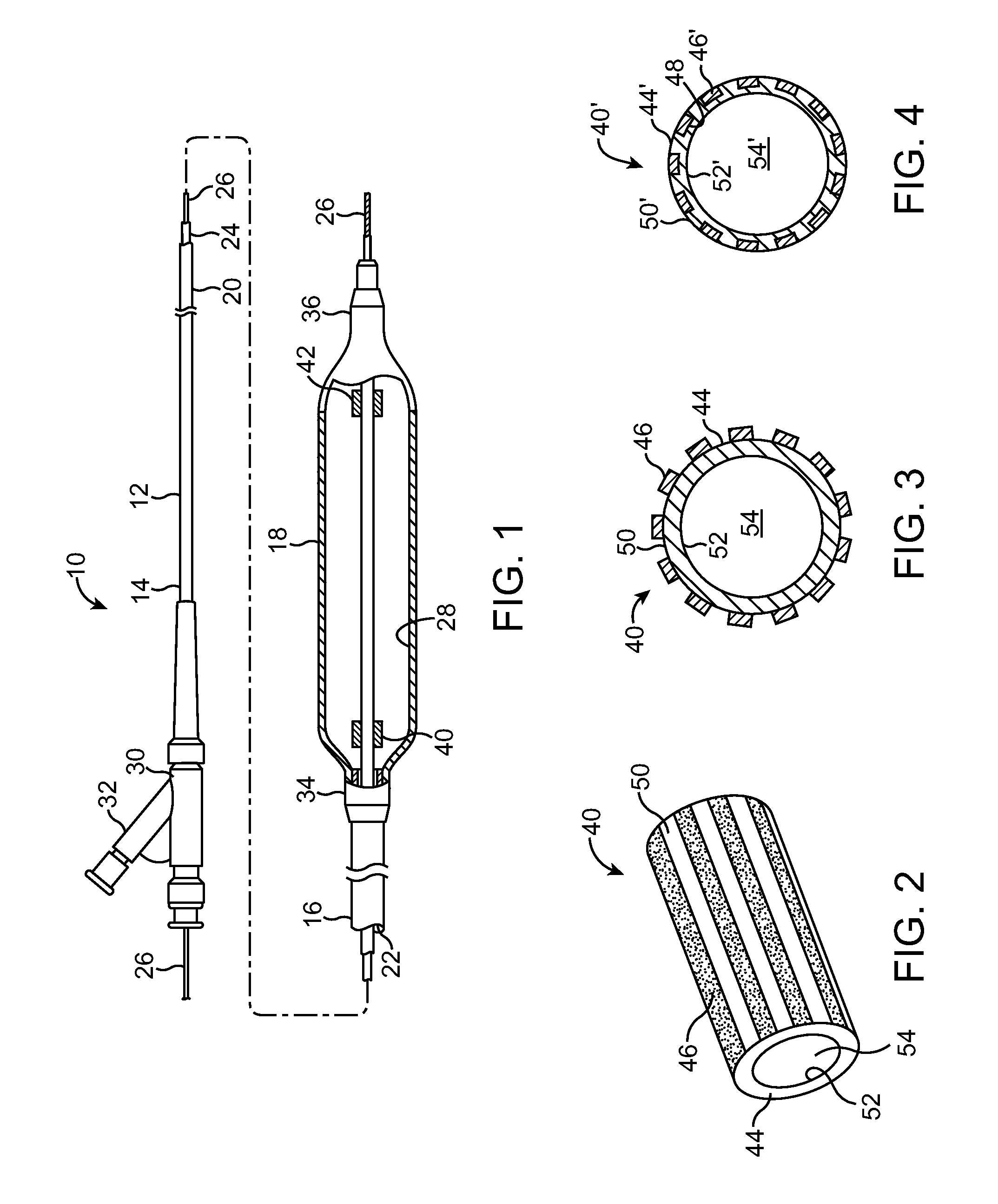
[0023]FIG. 1 illustrates an embodiment of an intraluminal catheter 10 of the invention, generally comprising an elongated shaft 12 having a proximal end 14 and a distal end 16, and a balloon 18 on a distal shaft section. In the embodiment illustrated in FIG. 1, the shaft 12 comprises an outer tubular member 20 defining an inflation lumen 22, and an inner tubular member 24 disposed within the outer tubular member and defining a guidewire lumen 25 configured to slidably receive a guidewire 26. In the illustrated embodiment, the coaxial relationship between outer tubular member 20 and inner tubular member 24 defines annular inflation lumen 22. A proximal portion 34 of balloon 18 is sealingly secured to a distal portion of outer tubular member 20 and a distal portion 36 of balloon 18 is sealingly secured to ...


PUM


Abstract

A radiopaque marker band includes a tube having an inner surface and an outer surface. The tube is made from a shape-memory material, such as a nickel-titanium alloy. A coating is disposed on at least a portion of the outer surface of the tube. The coating has a greater radiopacity that said shape-memory material. The coating may be applied in a plurality of bands on the outer surface of the tube.

Description

FIELD OF THE INVENTION[0001]This invention relates generally to radiopaque markers and, in particular, to a radiopaque marker band made of a shape-memory material coated with a radiopaque material.BACKGROUND OF THE INVENTION[0002]Many current procedures for treating a patient include the use of medical instruments that are inserted into the patient's vasculature, such as catheters for use in angioplasty and stenting procedures. In performing intravascular procedures, a physician typically uses a fluoroscope to visualize a patient's vascular structure. It is known to use one or more marker bands affixed to the medical instrument such as a catheter to assist the physician in guiding and positioning the catheter within the patient's vascular system.[0003]Known marker bands are typically constructed of a solid band of radiopaque material, such as platinum, iridium, tungsten, tantalum, gold, etc. and alloys thereof. Typically, the marker band is slipped around and onto a shaft of the cat...

Claims


Application Information

Patent Timeline
IPC IPC(8): A61M37/00
CPCA61L31/022A61L31/088A61L31/14A61L31/18A61L2400/16
Inventor KRIVORUCHKO, MICHAEL
Owner MEDTRONIC VASCULAR INC
Learn More