Machine tool control system

Inactive Publication Date: 2008-10-02
HAAS AUTOMATION
View PDF17 Cites 39 Cited by
  • Summary
  • Abstract
  • Description
  • Claims
  • Application Information

AI Technical Summary

Benefits of technology

[0004]The invention addresses the foregoing needs by providing a unique combination of components to form a machine tool control system. The invention facilitates the use of multiple

Problems solved by technology

As the capabilities of machine tools improve, the complexity of desired machining tasks increases.
This in

Method used


Image

  • Machine tool control system
  • Machine tool control system
  • Machine tool control system

Examples


Embodiment Construction

[0010]The detailed description of the invention set forth below in connection with the associated drawings is intended as a description of various embodiments of the invention and is not intended to represent the only embodiments in which the invention may be practiced. The detailed description includes specific details for the purpose of providing a thorough understanding of the invention. However, it will be apparent to those skilled in the art that the invention may be practiced without all of the specific details contained herein. In some instances, well known structures and components are shown in block diagram form in order to avoid obscuring the concepts of the invention.

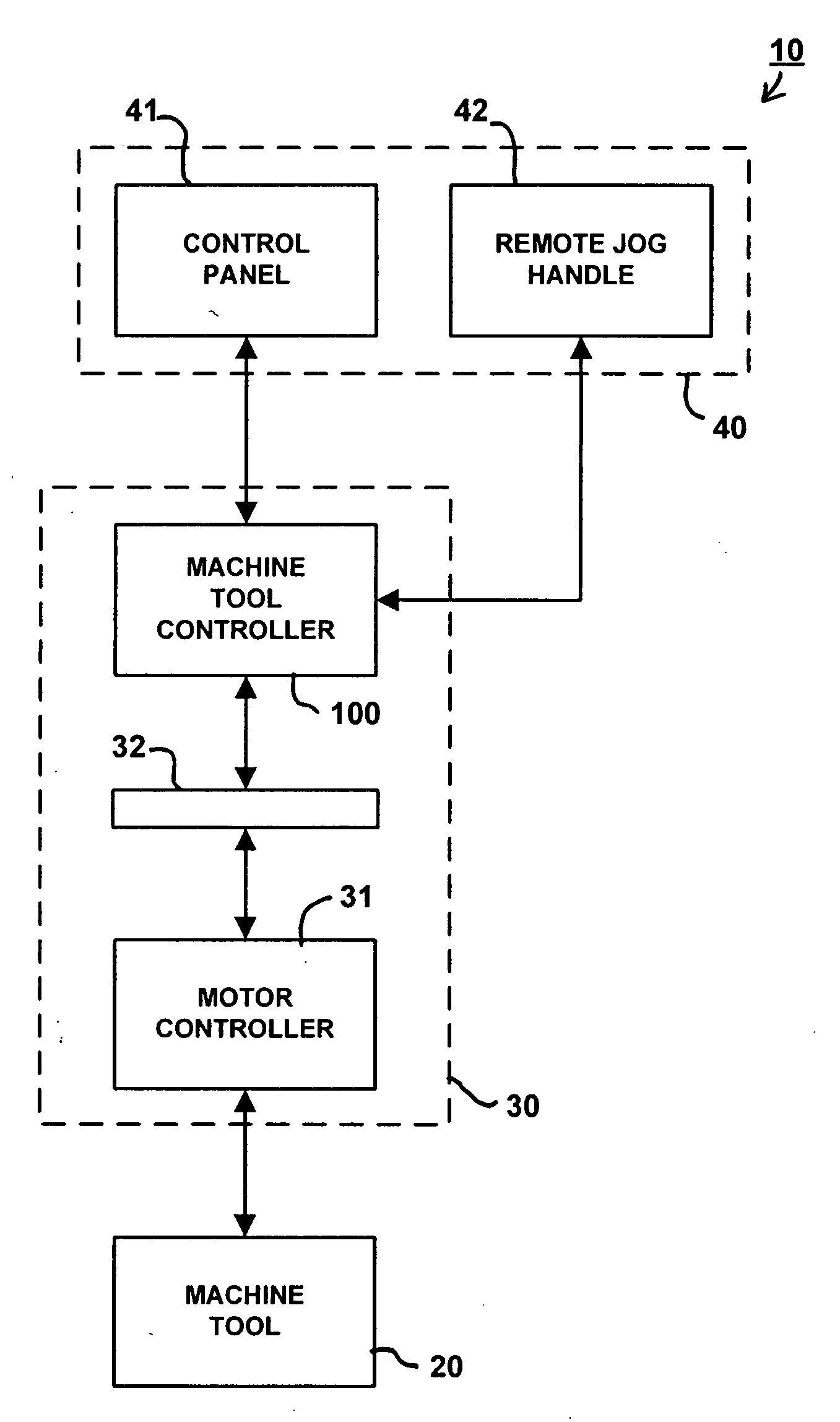
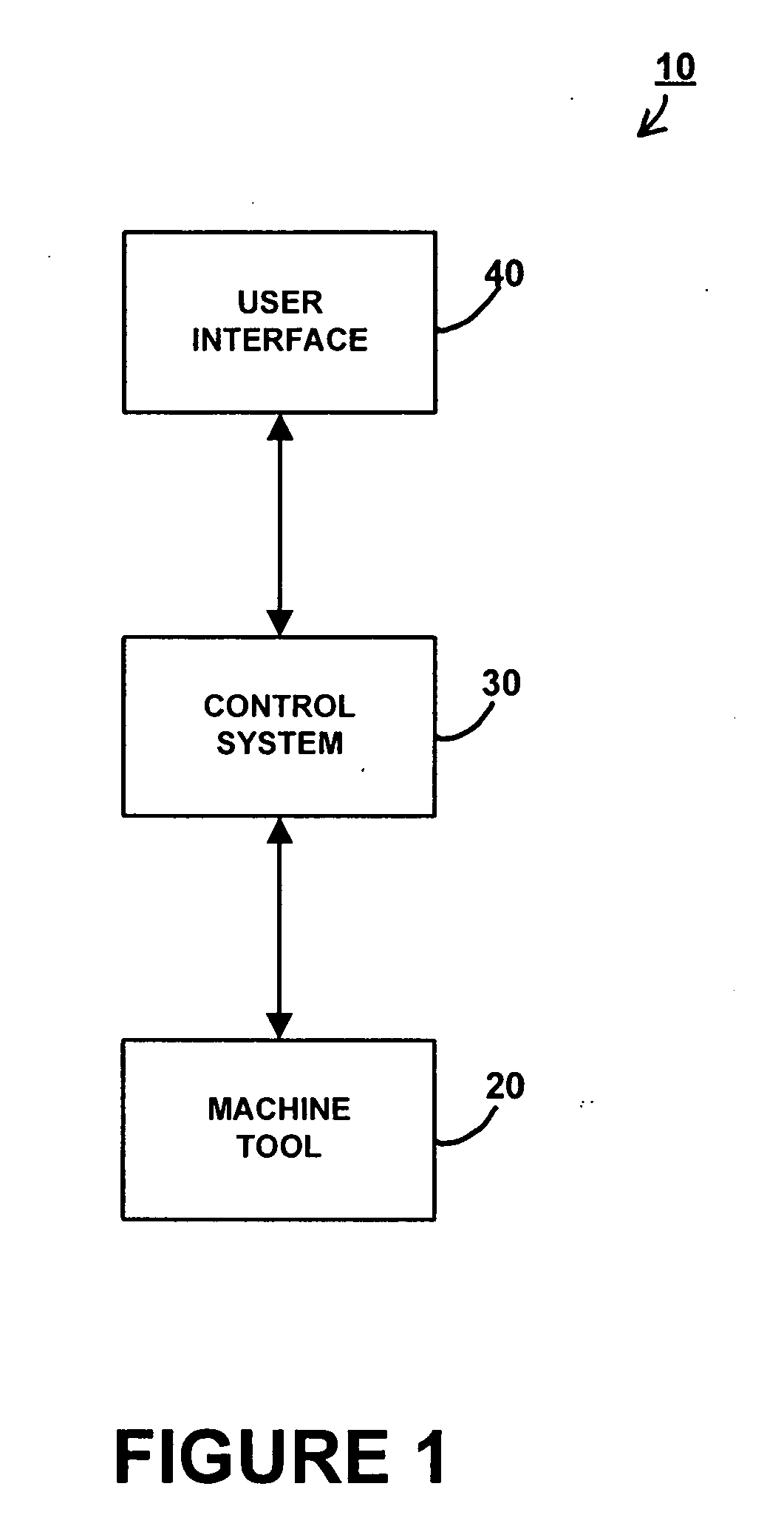
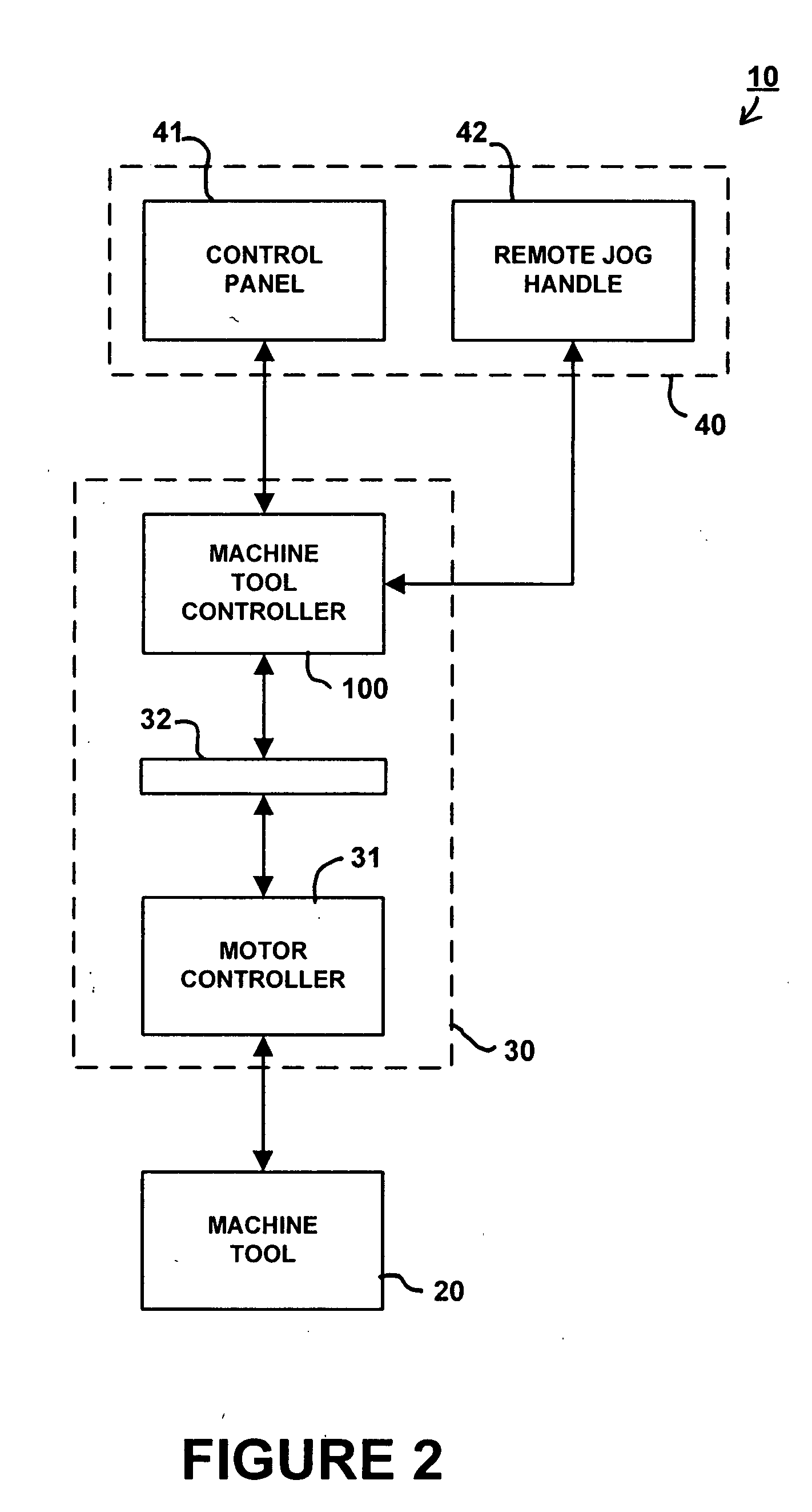
[0011]FIG. 1 is a block diagram depicting components of a CNC machine tool 10. As depicted in FIG. 1, CNC machine tool 10 includes a machine tool 20, a control system 30 and a user interface 40. Briefly, machine tool 20 processes a workpiece in accordance with commands received from control system 30. Control...


PUM


Abstract

A machine tool controller is provided that includes a processor configured to execute a sequence of instructions in accordance with an operating program and a user program. A volatile memory temporarily stores instructions and data during execution of the sequence of instructions by the processor, and is coupled to the processor via a first interface. A first non-volatile memory stores the operating program and is coupled to the processor via a second interface. A second non-volatile memory stores the user program and is coupled to the processor via a third interface. A video controller is configured to control a user display in accordance with display data generated by the processor and is coupled to the processor via a fourth interface. A dual-port memory is coupled to the processor via a fifth interface and couples a serial bus controller configured to control communications with an external device via a serial bus to the processor. An external bus interface is configured to communicate control commands for controlling a machine tool generated by the processor via an external bus and is coupled to said processor via a sixth interface.

Description

BACKGROUND OF THE INVENTION[0001]The invention concerns machine tools and, in particular, concerns a control system used in a computer numerical controlled (“CNC”) machine tool.[0002]CNC machine tools use a computer control system to control the operation of the machine tool. An operator selects a user program containing a sequence of instructions that is executed by the control system to operate the machine tool in a desired manner. Each instruction directs the machine tool to perform an action such as selecting a particular tool, positioning the tool or the workpiece, setting a rate of movement of the tool or the workpiece, etc. Using sequences of these instructions, CNC machine tools perform complex machining tasks with minimal human interaction. By shifting operation of the machine tool from a manual mode performed by a machinist to a computer controlled mode, complex machining tasks become repeatable with minimal variation between end products.[0003]As the capabilities of machi...

Claims


Application Information

Patent Timeline
IPC IPC(8): G06F19/00
CPCG05B19/414G05B2219/34006G05B2219/34024G05B2219/34072G05B2219/34076G05B2219/36109
Inventor JOHNSON, BARRY D.ZIERHUT, KURT P.
Owner HAAS AUTOMATION
Why Eureka
Try Eureka