Method and Apparatus for the Continuous Controlled Discharge of Solids

a technology of controlled solid discharge and continuous discharge, which is applied in the direction of liquid dispensing, fuel feeders, bottling operations, etc., can solve the problems of non-homogeneous mass flow of solid materials over the cross-section of the apparatus, temperature differences between regions which are flowing more quickly and more slowly, and no possible way of influencing local different discharge speed

Inactive Publication Date: 2008-10-09
MASCHFAB GUSTAV EIRICH
View PDF16 Cites 16 Cited by
  • Summary
  • Abstract
  • Description
  • Claims
  • Application Information

AI Technical Summary

Benefits of technology

[0008] The problem of the present invention is to provide a method and a discharge apparatus for a solids silo as well as a solids silo which can be equipped with such a discharge apparatus, which permit a controllable solids discharge which is regular over the cross-section of the silo, and thus permit the production of bulk materials which are treated physically or chemically when flowing through the silo, being in particular heated or cooled, with properties which are as homogeneous as possible, in particular with slight temperature differences. In addition in its preferred configuration the invention permits automatic adaptation to changing flow properties in respect of the intake substances used.

Problems solved by technology

In the case of bulk materials which flow very poorly, those known measures nonetheless frequently still result in a non-homogeneous mass flow of the solid material over the cross-section of the apparatus.
As the current which is passed through the bulk material has a tendency to flow along the path of least resistance, when dealing with an irregular mass flow across the cross-section of the silo-form apparatus, that results in temperature differences between regions which are flowing more quickly and more slowly.
Particularly in a situation involving changing flow properties in respect of the intake substances, due for example to changing intake temperature, material moisture content or particle size distribution, there is hitherto no possible way of influencing the locally different discharge speed, which arises as a result thereof, from the solids silo.

Method used


Image

  • Method and Apparatus for the Continuous Controlled Discharge of Solids
  • Method and Apparatus for the Continuous Controlled Discharge of Solids
  • Method and Apparatus for the Continuous Controlled Discharge of Solids

Examples


Embodiment Construction

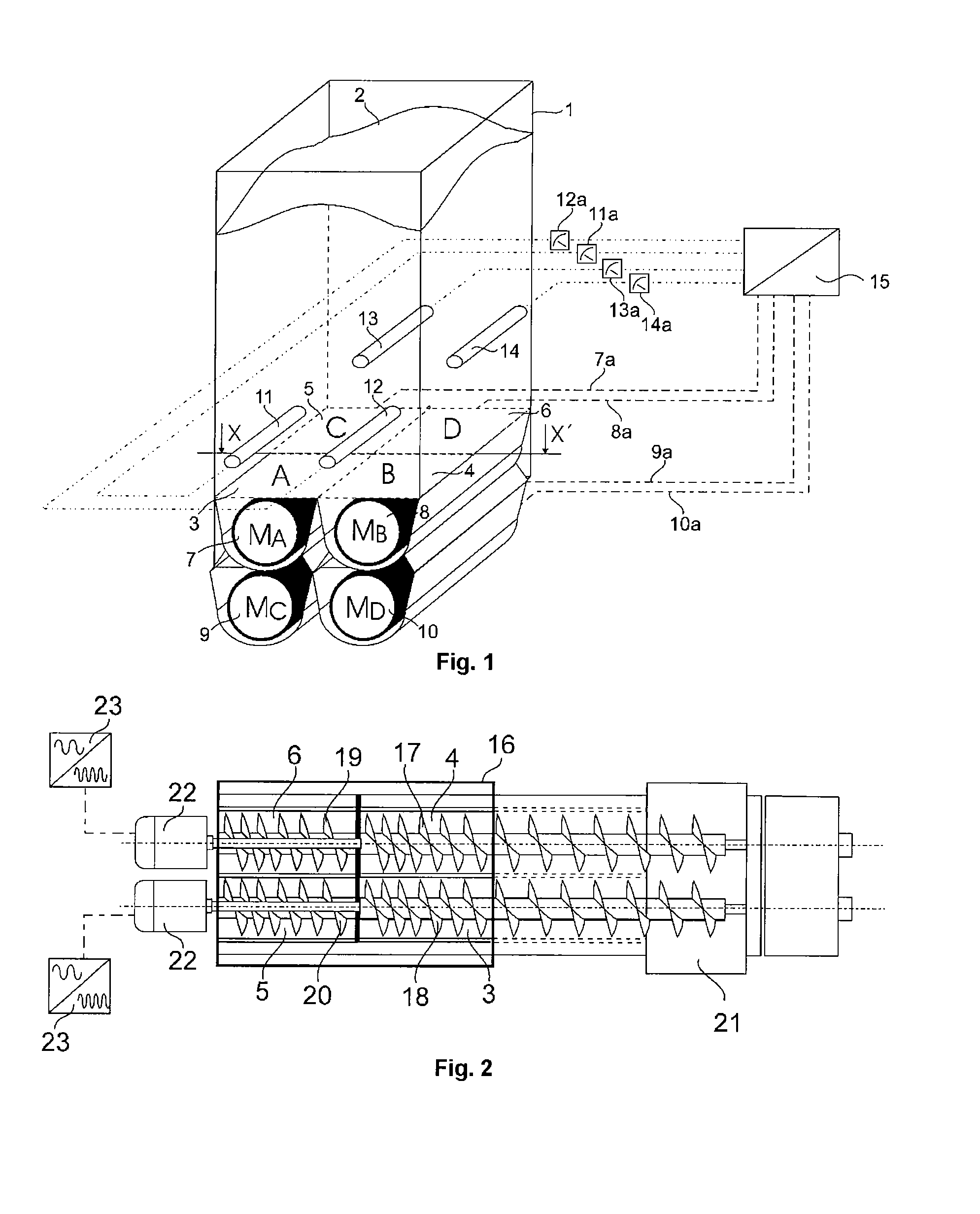
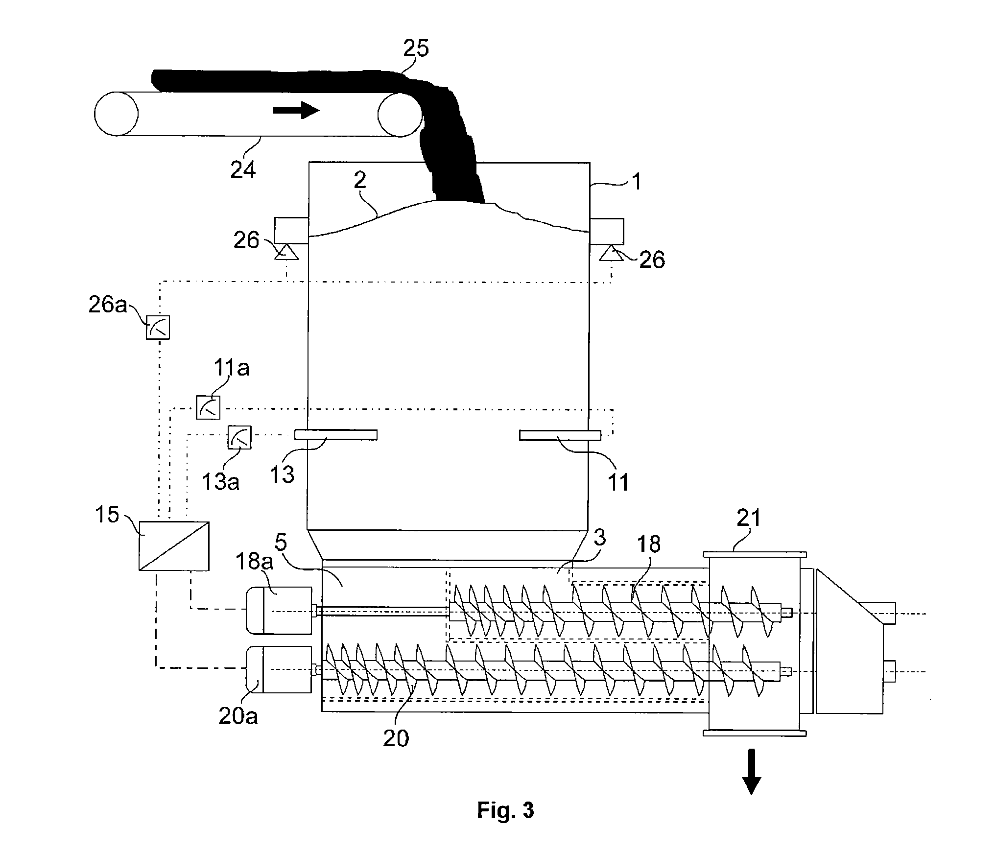
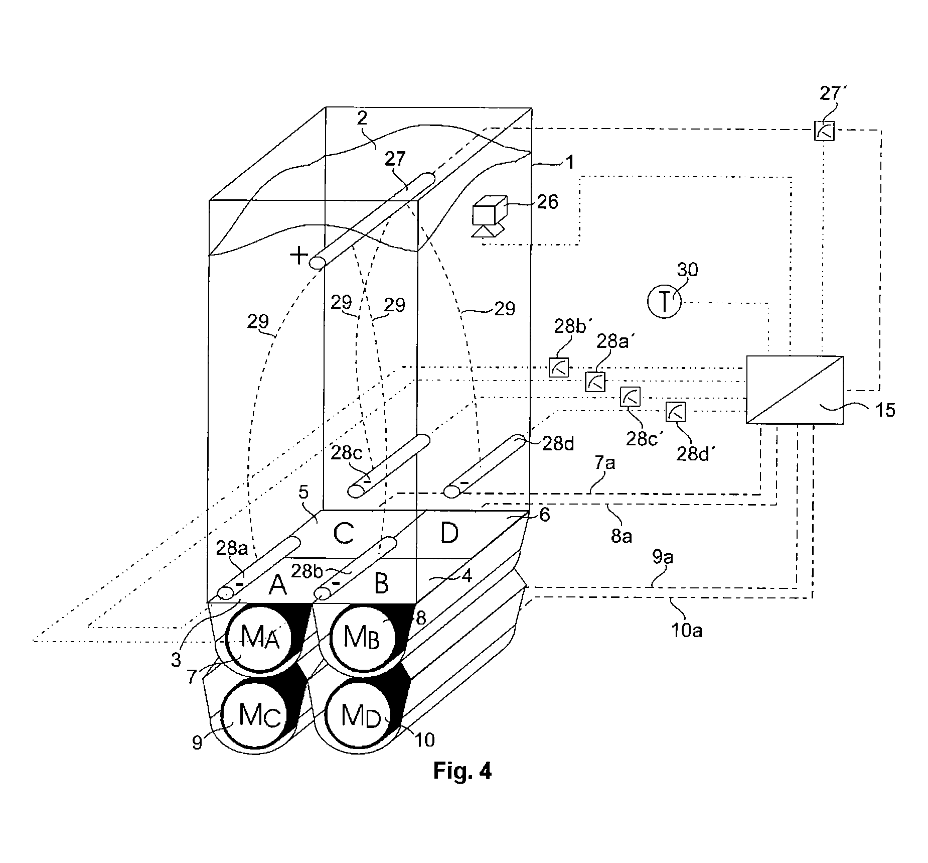
[0041]FIG. 5 shows a variant of FIG. 4 and FIG. 1, in which heating or cooling of the solid within the silo 1 is effected by way of example by way of heat exchanger elements 32 through which pass vapour, thermal oil or cooling fluid and which in a further variant could also be electrically heated. The solid mass flow in each portion 3, 4, 5 and 6 is detected as shown in FIG. 1 by way of a plurality of mass flow sensors 11, 12, 13, 14 and the signals 11a, 12a, 13a and 14a are fed to a signal evaluation and control unit 15 which generates therefrom corresponding setting signals for the discharge devices 7, 8, 9 and 10 as set forth in the description relating to FIG. 1. The power input 33 at the heating or cooling elements 32 within the silo, controllable for example by way of the through-flow of the heating or cooling medium, is effected in dependence on the measured final temperature 30 at the discharge of the withdrawal screws.

[0042]FIG. 6 shows a further variant of FIG. 5, in whic...


PUM


Abstract

It is known that poorly-flowing solid materials can lead to an inhomogeneous mass flow of the solid across the discharge cross-section of a silo. If the solid in the silo is also heated or cooled the uneven mass flow can lead, for example, to local variations in temperature and / or hence to varying product properties. According to the invention, the above problem may be resolved, whereby a method and a discharge device for a solids silo and a solids silo are disclosed, permitting a controllable solids discharge evenly across the cross-section of the silo. The cross-section of the silo discharge is divided into several, preferably equivalent, partial cross-sections to which a continuously controllable discharge device is connected. The solid flow discharged from the controllable discharge devices can be collected on a continuous conveyor arranged therebelow and removed. The even solid mass discharge from the continuous discharge devices is controlled, depending on measured signals from several equivalent sensors, recording the local mass flow in the corresponding partial sections of the silo, by means of the conveyor power of the discharge device, relating to each sensor. Where electrically-conducting solids are used which are to be heated in the silo using electrodes by means of resistance heating, the control of the discharge devices is achieved with the measured current at the electrodes.

Description

TECHNICAL FIELD [0001] The present invention concerns a method of discharging a solid from a silo with a polygonal or round discharge cross-section, wherein the solid flows continuously through the silo. [0002] The invention further concerns a discharge apparatus for a solids silo having a polygonal or round discharge cross-section, as well as a solids silo, wherein the silo is designed for a solid to flow therethrough. STATE OF THE ART [0003] In regard to the metered withdrawal from silos with a rectangular or square discharge opening, it is known that, when using a screw conveyor in which the screw is of a constant core and outside diameter and has a constant screw pitch, the bulk material is withdrawn only at the rearward end of the silo while a dead zone is formed in the forward region of the silo. By virtue of adaptation of the screw geometry, for example by a reduction in the core diameter in the conveyor direction and an increase in the outside diameter or the screw pitch, th...

Claims


Application Information

Patent Timeline
Patent Type & Authority Applications(United States)
IPC IPC(8): B01J8/00H05B3/60B65G65/46B65G65/48B65G69/10H05B3/00
CPCB01J8/002B01J8/003B01J2208/00061B01J2208/00415B01J2208/0061B01J2208/00752B01J2219/00191B65G65/46B65G65/4881B65G69/10H05B3/0009H05B3/60
Inventor ADELMANN, DIETERGERL, STEFAN
Owner MASCHFAB GUSTAV EIRICH
Why Eureka
Try Eureka