Buoyancy Vehicle Apparatus to Create Electrical Power
a vehicle and vehicle technology, applied in mechanical devices, electric generator control, machines/engines, etc., can solve the problems of difficulty in controlling when enough power will be provided to the grid, inability to achieve consistent output, and trouble in meeting energy demand overnigh
- Summary
- Abstract
- Description
- Claims
- Application Information
AI Technical Summary
Benefits of technology
Problems solved by technology
Method used
Image

Examples
first embodiment
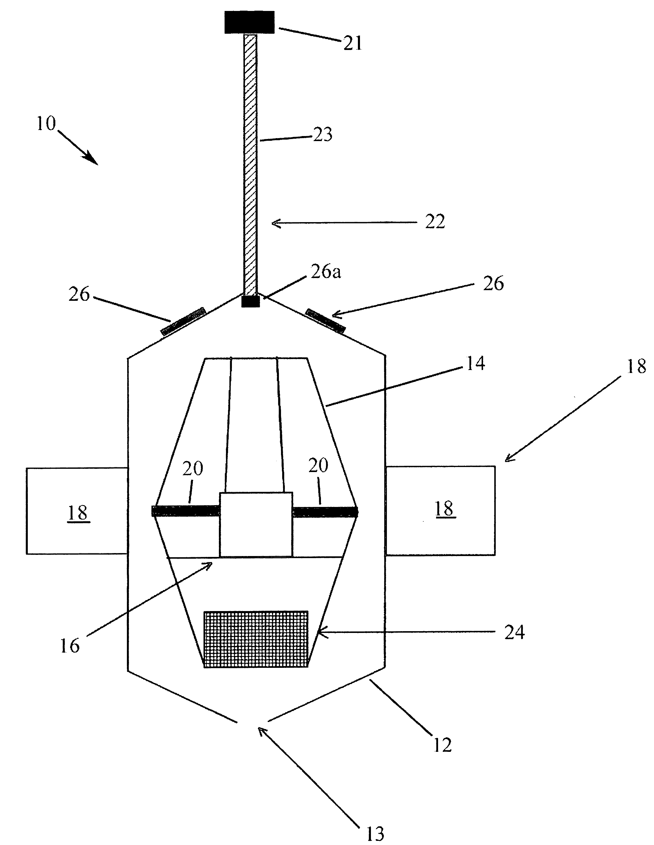
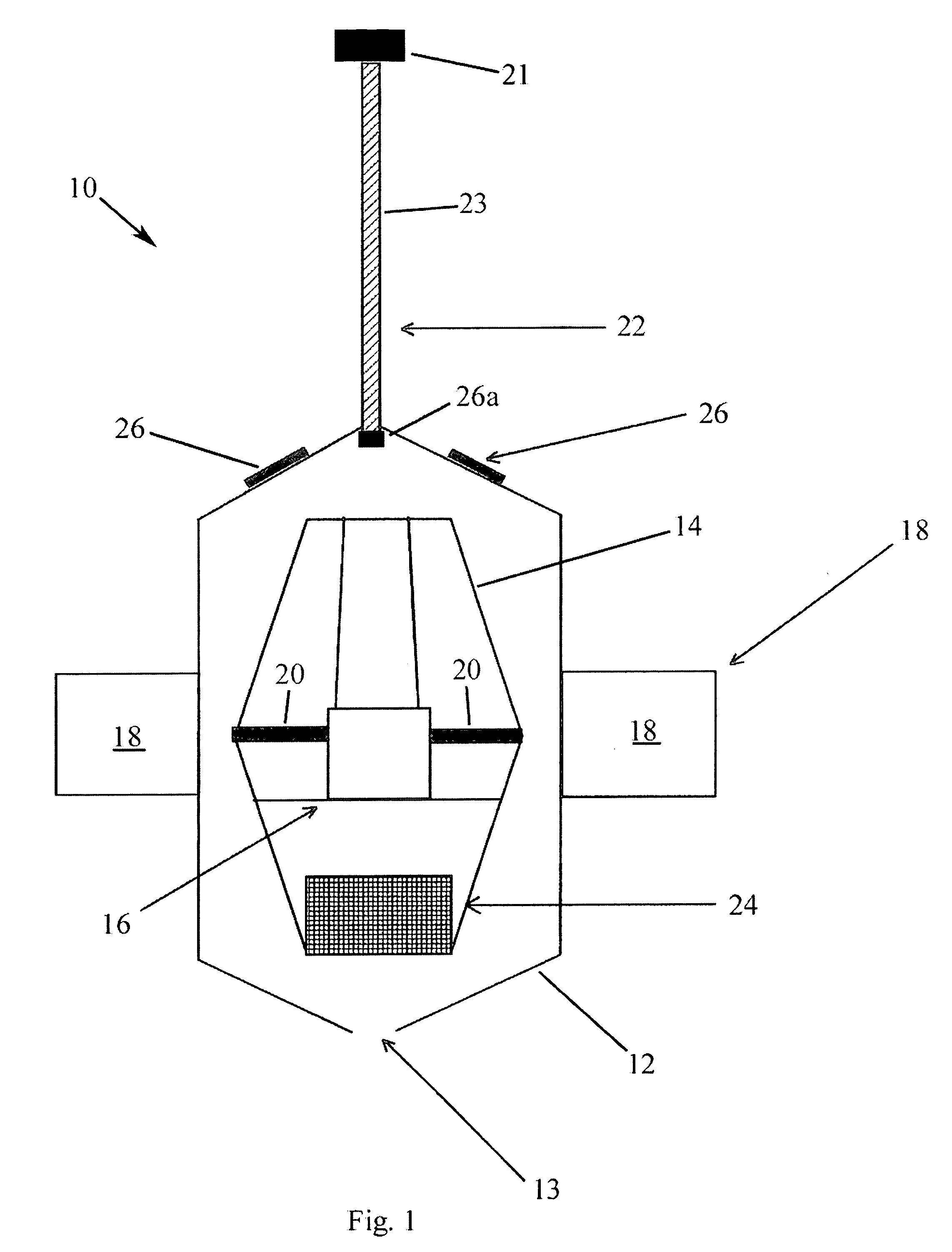
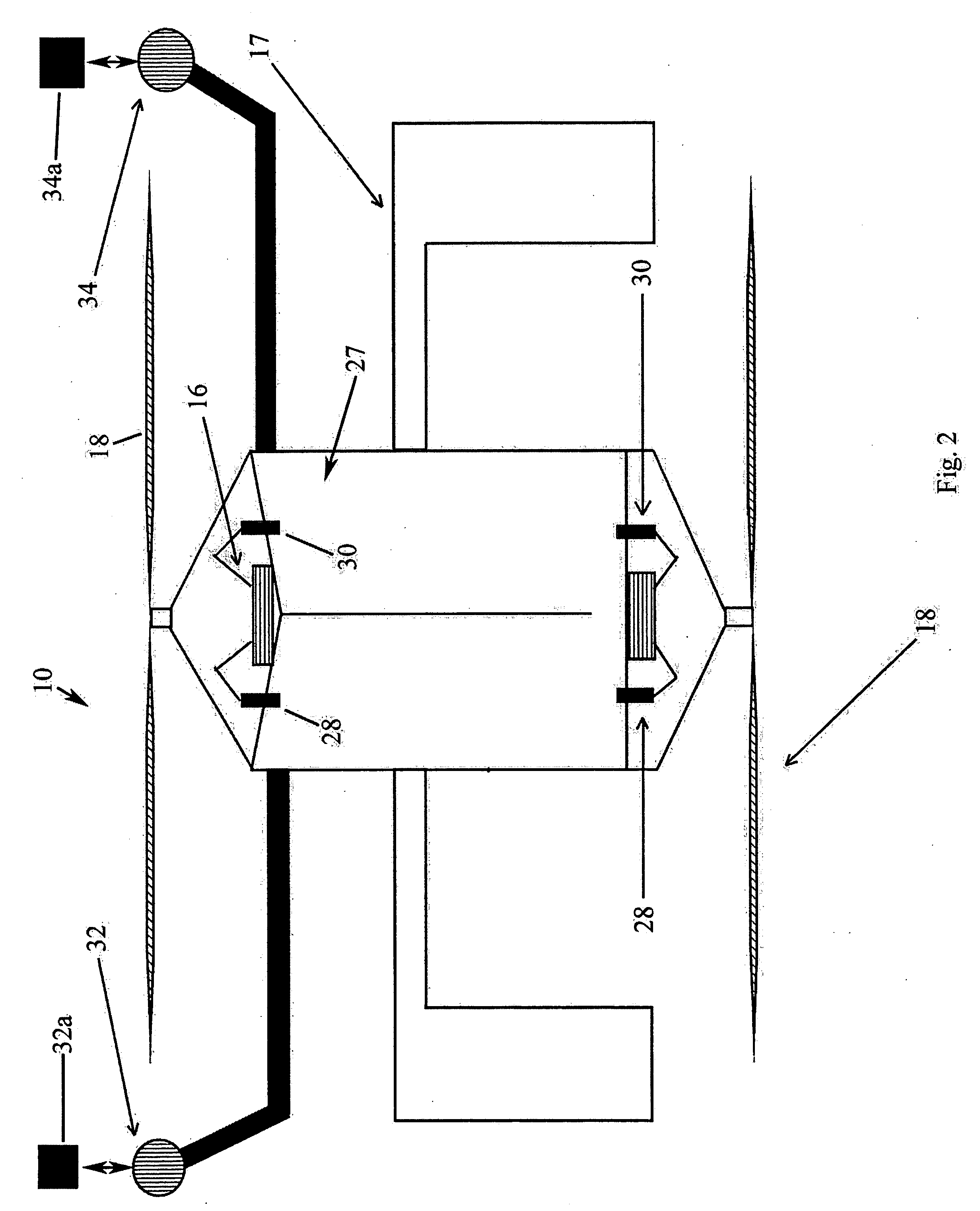
[0017]A buoyancy vehicle apparatus 10 that creates electrical power from the movement of the apparatus 10 through a fluid as the apparatus 10 cycles negative buoyancy to positive buoyancy is illustrated in the attached figures. In particular, a first embodiment is illustrated in FIG. 1. The apparatus 10 is positioned relative to a collection of the fluid, such as a water in a water tank 11, as shown in FIG. 3. The apparatus 10 has an outer housing 12 that surrounds an interior, air-filled housing or ballast 14. One or more generators 16 are positioned in the interior housing 14, with each generator 16 connected to an driving or agitating mechanism, such as a propeller having blades or a turbine 18, via a shaft or axle 19. The design of each generator 16 is known to persons having ordinary skill in the art, and typically includes a simple device that includes an armature to move a magnet near a wire to create a steady flow of electrons. That is, the generator 16 converts mechanical e...
second embodiment
[0033]the facility 40 is illustrated in FIG. 9. In this embodiment, the facility 40 takes advantage of air and electrical wiring coming from the bottom of the tank 11 as opposed to the top of the tank 11 as shown in FIG. 7. Multiple apparatuses 10 are shown functioning as in FIG. 7, but when this embodiment, each apparatus 10 descends to the bottom of the tank 11. Once at the bottom, the air is pumped into the interior housing 14 and then released at the top of the tank 11 as in previous examples. The electrical wire 22 could come out the bottom or top of the outer housing 12, with the user testing the various embodiments to determine which is most efficient.
[0034]In operation, it is desired that the generator 16 and propeller 18 will move in the water at the rate of 2 meters / second to provide the desired electrical output. This rate is no problem for this design and is able to produce up to 35 kW per hour. It is estimated that a water tank 11 could be used (in-ground or above groun...
PUM
 Abstract
Description
Claims
Application Information
 - R&D
- Intellectual Property
- Life Sciences
- Materials
- Tech Scout
- Unparalleled Data Quality
- Higher Quality Content
- 60% Fewer Hallucinations
Browse by: Latest US Patents, China's latest patents, Technical Efficacy Thesaurus, Application Domain, Technology Topic, Popular Technical Reports.
© 2025 PatSnap. All rights reserved.Legal|Privacy policy|Modern Slavery Act Transparency Statement|Sitemap|About US| Contact US: help@patsnap.com