
Ion generating device and image forming apparatus including same

a technology of generating device and image forming apparatus, which is applied in the direction of corona discharge, electrographic process, instruments, etc., can solve the problems of difficult to obtain mica raw mica having a large amount of space, difficult to miniaturize the charging device, and insufficiently meet the demand for miniaturization of ion generating device as corona charging device and roller-type contact device described above, etc., to achieve easy manufacturing of creeping, reduce manufacturing cost, and increase the discharge amoun

Inactive Publication Date: 2008-10-09
SHARP KK
View PDF6 Cites 2 Cited by
  • Summary
  • Abstract
  • Description
  • Claims
  • Application Information

AI Technical Summary

Benefits of technology

[0027]This makes it possible to efficiently use a dielectric material that has conventionally been wastefully disposed with an undeteriorated area remaining thereon. This makes it possible to extend the life of a creeping discharge element or an ion generating device while using a dielectric material of the same size. Moreover, this makes it possible to reduce the total cost including maintenance cost for replacing the creeping discharge element and the ion generating device.
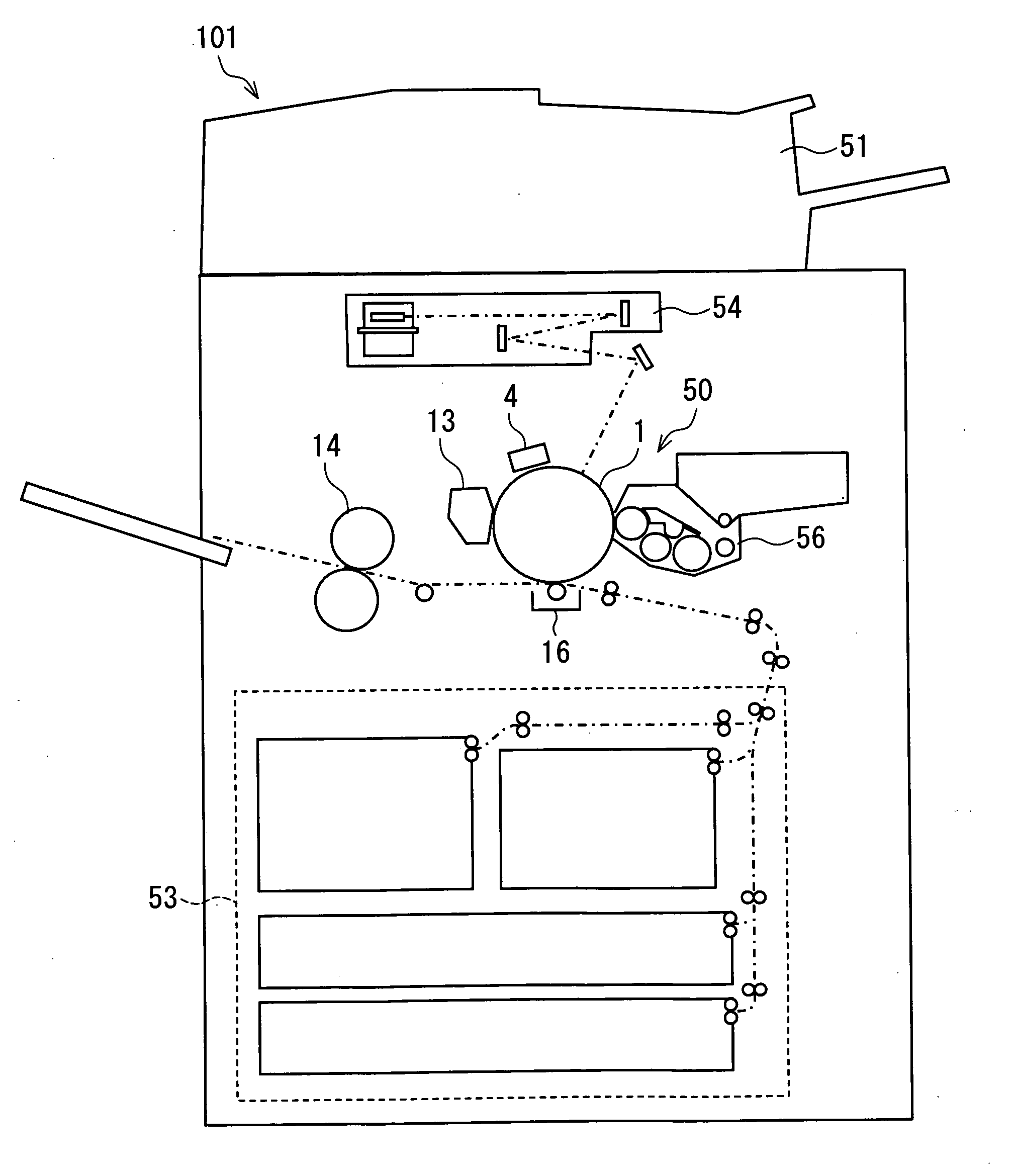
[0041]By using an ion generating device of the present invention as a toner precharging device for giving electric charge to toner contained in a developing device for developing an electrostatic latent image, an image of high quality can be obtained while holding down the cost of manufacturing and the running cost.

Problems solved by technology

In reality, such ion generating devices as corona charging devices and roller-type contact device described above cannot sufficiently meet the demand for miniaturization.
This makes it difficult to miniaturize the charging device.
However, it is very difficult to obtain raw mica having a large amount of space, and such raw mica is expensive.
Further, ceramic is expensive, albeit not as expensive as raw mica.
Moreover, ceramic is prone to breakages and cracks.
This makes it difficult to shape ceramic into a thin plate.
That part of the minute hole 106 which has grown larger or contains water deteriorates in insulation resistance, and therefore becomes incapable of discharging.
This makes it impossible to ensure uniformity in discharge, thereby causing nonuniformity in ion generating ability.
However, even in the arrangement, described in Patent Documents 1 and 2, in which the discharge electrode and the dielectric material are coated with the inorganic coating agent, it is hard to say that the life of the ion generating device is sufficiently long.
Furthermore, such a conventional ion generating device as described in Patent Documents 1 and 2 has problems with cost of manufacturing and running cost.
This inevitably causes a rise in cost of manufacturing.
This causes an increase in power consumption, and shortens the life of an ion generating device or a creeping discharge element by accelerating deterioration of the dielectric material 101, thereby causing a rise in running cost.

Method used


Image

  • Ion generating device and image forming apparatus including same
  • Ion generating device and image forming apparatus including same
  • Ion generating device and image forming apparatus including same

Examples


embodiment 1

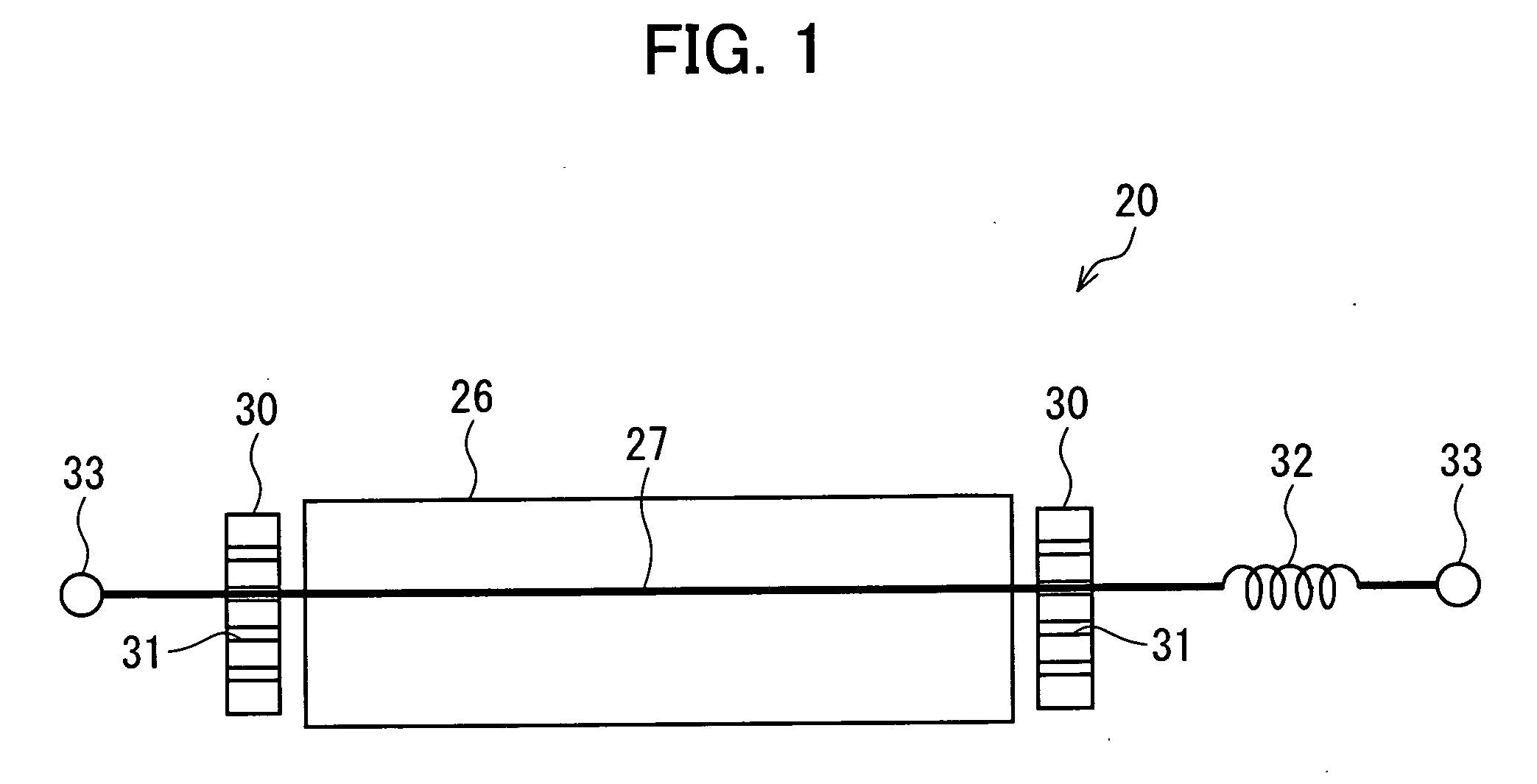
[0060]An embodiment of the present invention will be described below with reference to FIGS. 1 through 7. The embodiment described below is a specific example of the present invention, and does not limit the technical scope of the present invention.

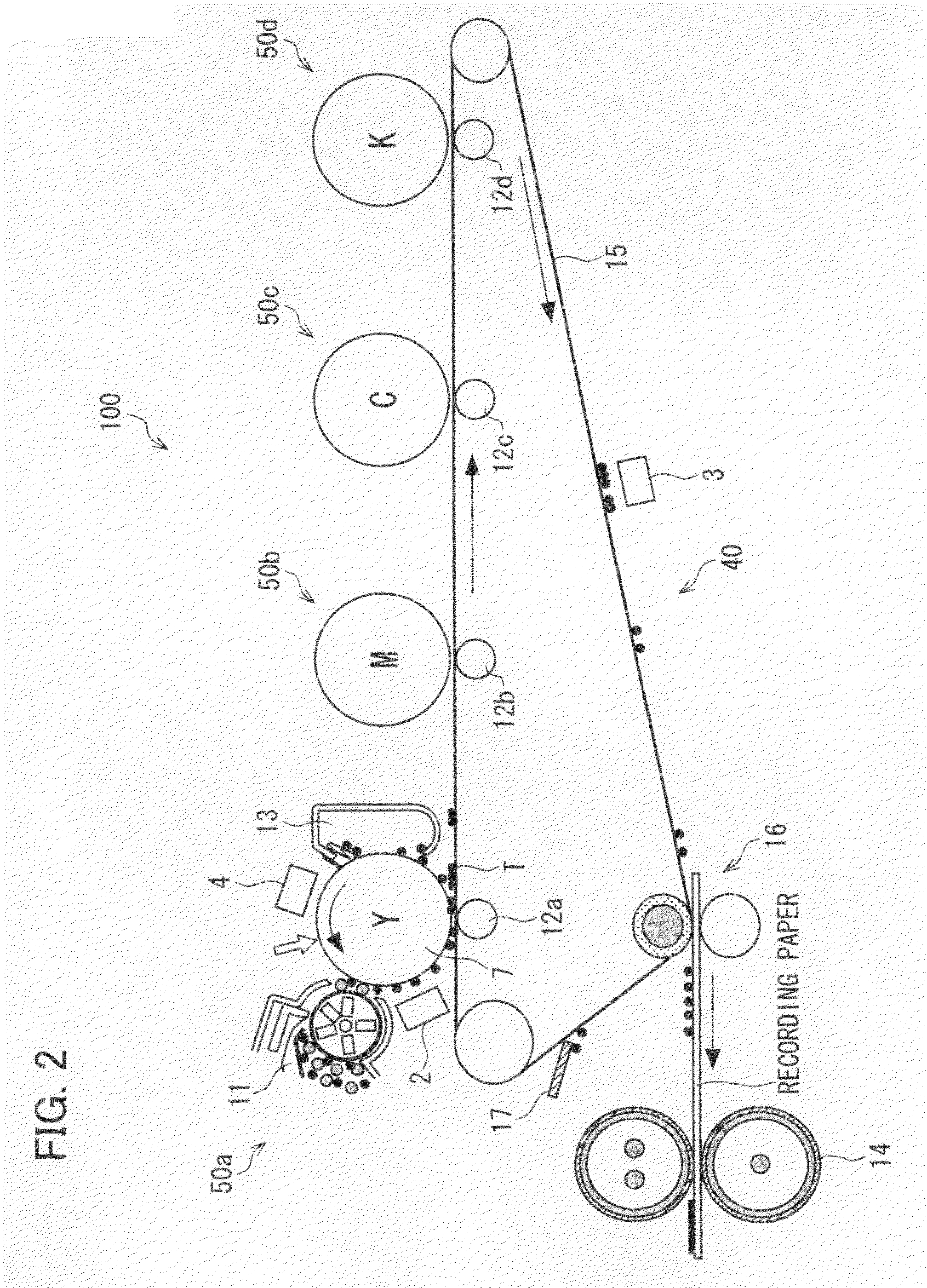
[0061]First, an overall arrangement of an electrophotographic image forming apparatus 100 according to the present embodiment will be described with reference to FIG. 2. The image forming apparatus 100 is a printer of a tandem type and of an intermediate transfer type, and can form a full-color image.

[0062]As shown in FIG. 2, the image forming apparatus 100 includes: four visible-image forming units 50a to 50d respectively corresponding to four colors (C, M, Y, and K); a transfer unit 40; and a fixing device 14.

[0063]The transfer unit 40 includes an intermediate transfer belt 15 (image carrier), four first transfer devices 12a to 12d, a charging device 3 for charging before a second transfer, a second transfer device 16, and a cleaning de...

embodiment 2

[0156]Another embodiment of the present invention will be described below with reference to FIGS. 9 and 10. For convenience of explanation, members having the same functions as those used in Embodiment 1 will be given the same reference numerals and will not be described below.

[0157]An image forming apparatus of the present embodiment differs from the image forming apparatus 100 of Embodiment 1 in terms of ion generating devices that are used as a charging device 2 for charging before a first transfer, a charging device 3 for charging before a second transfer, and a latent image charging device 4. In each ion generating device 28 provided in the image forming apparatus of the present embodiment, the position of a discharge electrode 27 with respect to a dielectric material 26 can be automatically switched.

[0158]The following describes only parts different from those of the ion generating device 1. As shown in FIG. 9, the ion generating device 28 has a positioning member 35 provided ...

embodiment 3

[0167]Another embodiment of the present invention will be described below with reference to FIGS. 11 through 13. For convenience of explanation, members having the same functions as those used in Embodiments 1 and 2 will be given the same reference numerals and will not be described below.

[0168]An image forming apparatus of the present embodiment differs from the image forming apparatus 100 of Embodiment 1 in terms of ion generating devices that are used as a charging device 2 for charging before a first transfer, a charging device 3 for charging before a second transfer, and a latent image charging device 4. In each ion generating device 42 provided in the image forming apparatus of the present embodiment, the position of a discharge electrode 27 with respect to a dielectric material 26 can be automatically switched as in the ion generating device 28 of Embodiment 2.

[0169]The following describes only parts different from those of the ion generating device 28. As shown in FIG. 11, t...


PUM


Abstract

An ion generating device provided in an image forming apparatus of the present invention as a charging device for charging before a first transfer, a charging device for charging before a second transfer, or a charge device for charging an electrostatic latent image is arranged such that a discharge electrode can move with respect to a dielectric material and the relative positions of the discharge electrode and the dielectric material can be changed. This makes it possible to provide: a long-life ion generating device whose life has been extended by making effective use of a dielectric material; and an image forming apparatus including the ion generating device.

Description

[0001]This Nonprovisional application claims priority under 35 U.S.C. § 119(a) on patent application Ser. Nos. 09908 / 2007 and 099909 / 2007 filed in Japan on Apr. 5, 2007, the entire contents of which are hereby incorporated by reference.FIELD OF THE INVENTION[0002]The present invention relates to an ion generating device that generates ions along with creeping discharge and an image forming apparatus, such as a copier, a facsimile machine, or a printer, which includes the ion generating device.BACKGROUND OF THE INVENTION[0003]Some image forming apparatuses such as copiers, printers, and facsimile machines employ an electrophotographic method as a recording method, and the market for such image forming apparatuses have been rapidly growing.[0004]Conventionally, in such an image forming apparatus employing an electrophotographic method, ion generating devices have been used as a charging device for charging a photoreceptor or the like, as an electricity-removing device for removing ele...

Claims


Application Information

Patent Timeline
Patent Type & Authority Applications(United States)
IPC IPC(8): B41J2/415H01J47/02
CPCB41J2/415G03G15/0291
Inventor HIRAI, MASASHINAKANO, KUNIAKIISHIKAWA, KAZUAKI
Owner SHARP KK
Learn More