Extruder

a technology of extruder and spherical plate, which is applied in the field of extruder, can solve the problems of virtually unclogging the porous wall portion, and achieve the effect of increasing the previously attainable throughput of such powder

Active Publication Date: 2008-10-09
COPERION
View PDF6 Cites 31 Cited by
  • Summary
  • Abstract
  • Description
  • Claims
  • Application Information

AI Technical Summary

Benefits of technology

[0008]It is the object of the invention to design an extruder of the generic type in a way as to ensure a problem-free operation even of a partially filled and therefore substantiall

Problems solved by technology

Due to the fact that a layer of powdery bulk material of an even thickness is created on the gas-permeable wall portion by applying a low pressure without extracting any of the powdery bulk material, no additional procedures, such as gas-solid separation and re-feeding

Method used


Image

  • Extruder
  • Extruder
  • Extruder

Examples


Embodiment Construction

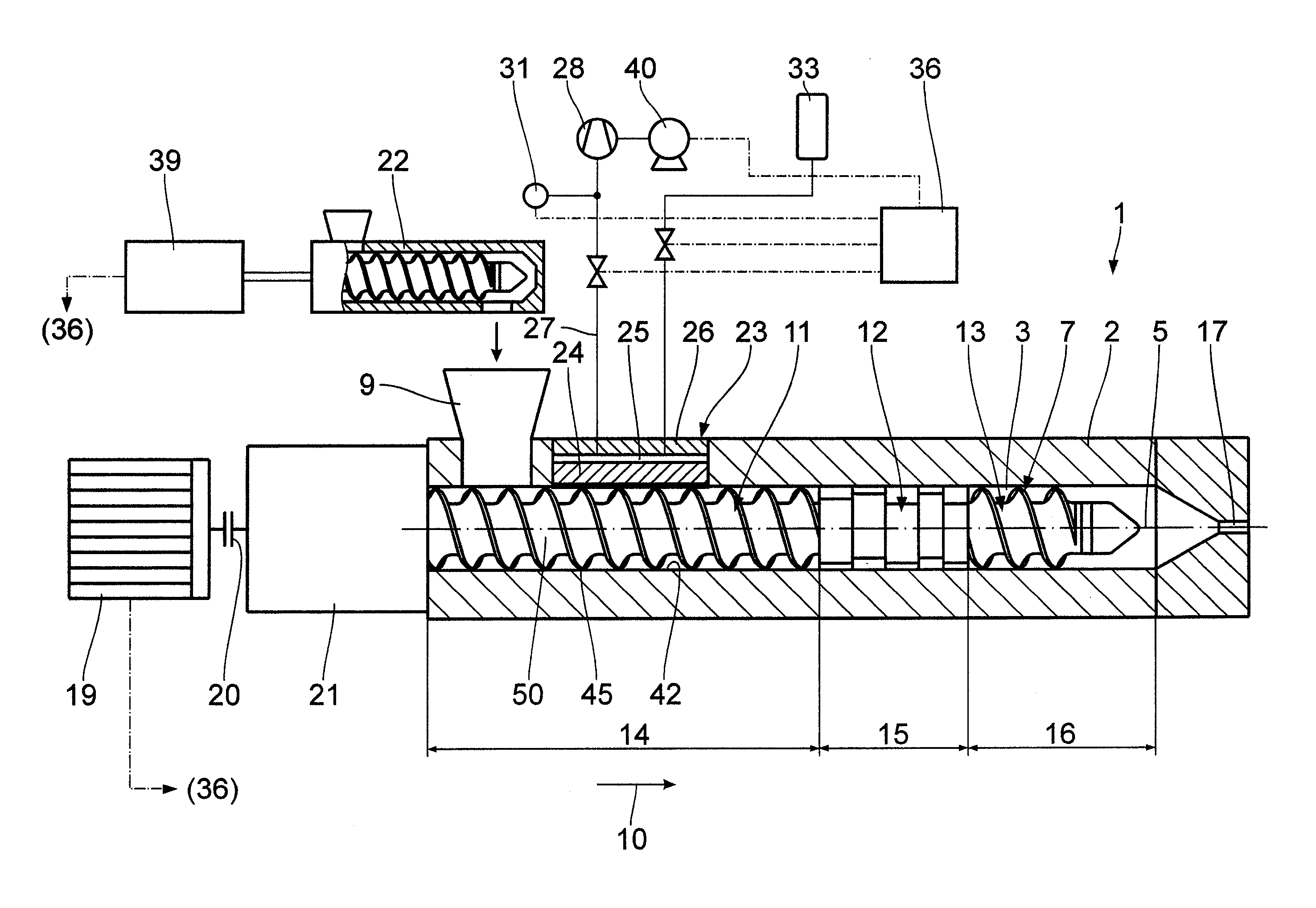
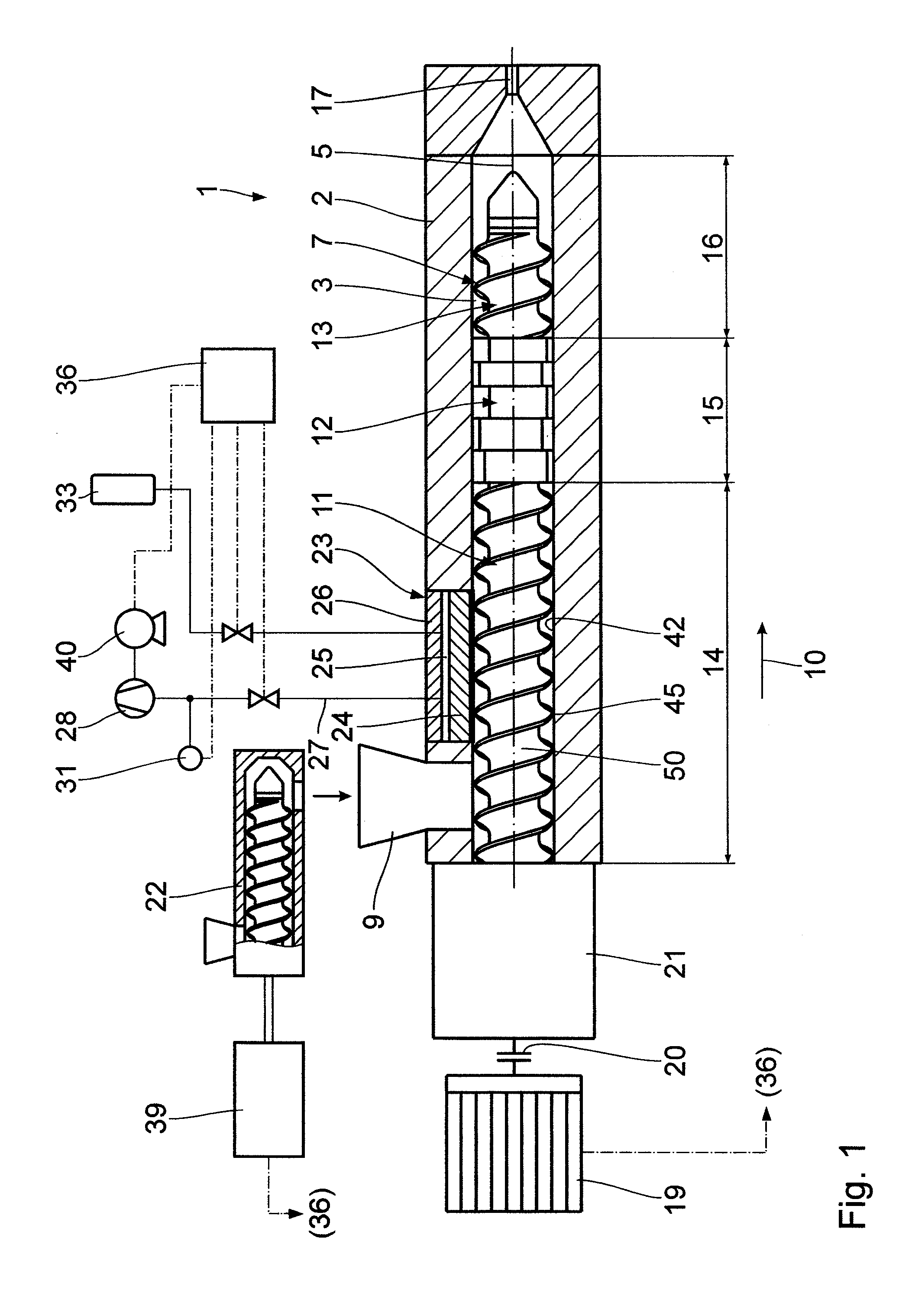
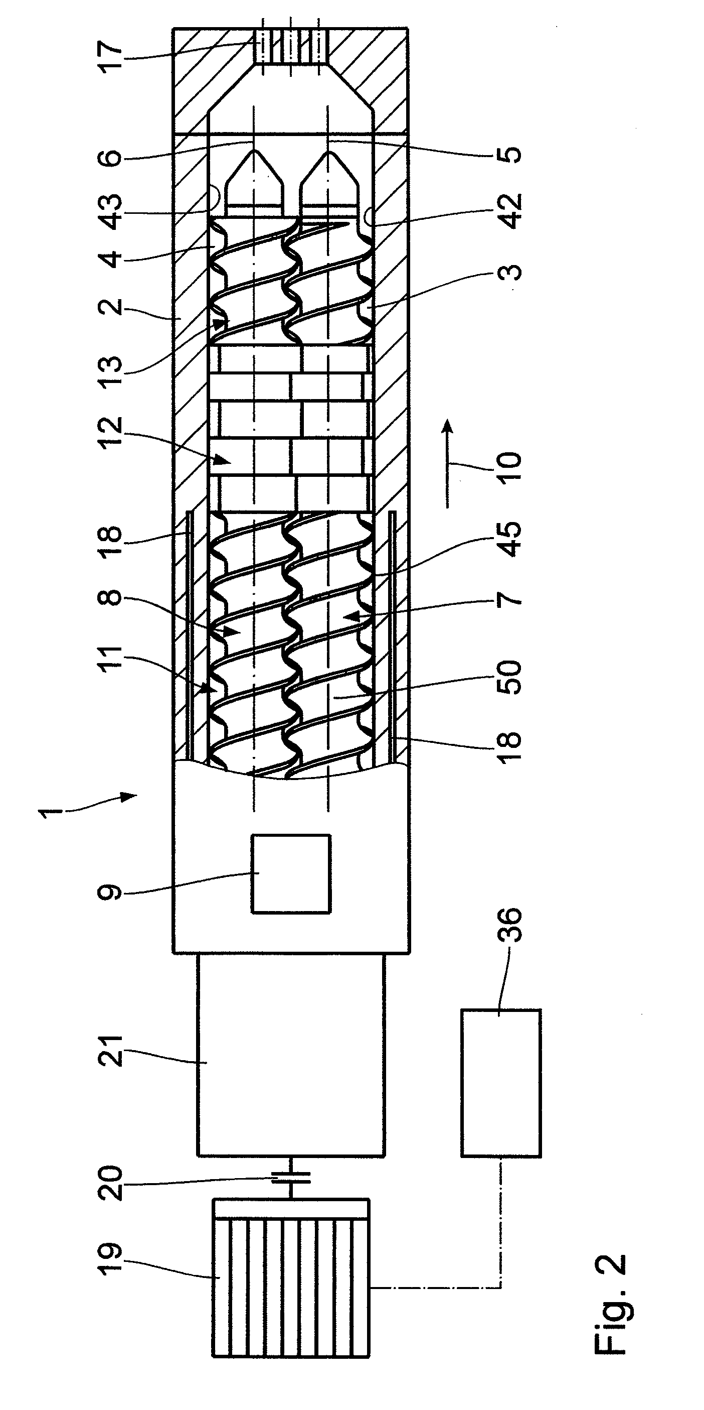
[0017]The extrusion system shown in the drawing has an extruder 1. In the housing 2 thereof, which is usually composed of several housing sections, bores 3, 4 are formed that inter-engage in the manner of a figure eight and have parallel axes 5, 6. Two screws 7, 8 are disposed in the housing bores 3, 4. The screws are closely intermeshing screws 7, 8 rotating in the same direction. On one end—the left-hand end in FIGS. 1 and 2—a feed hopper 9 opens into the bores 3, 4. Seen in a transport direction 10, starting from the feed hopper 9, the screws 7, 8 are provided with a first screw conveyor portion 11, a kneading-disk portion 12 adjacent thereto and another, second screw conveyor portion 13.

[0018]The first screw conveyor portion 11 extends over an inlet zone 14 acting as a solid conveying zone. In this embodiment, the kneading-disk portion 12 defines a melting zone 15. The second screw conveyor portion 13 defines a pressure build-up zone 16. At the end of the housing 2, a discharge ...


PUM

PropertyMeasurementUnit
Lengthaaaaaaaaaa
Grain sizeaaaaaaaaaa
Pressureaaaaaaaaaa

Abstract

An extruder with a housing comprising parallel, partially inter-engaging bores and screws disposed therein is used when applying a method of feeding powdery bulk materials into such an extruder. A solid transport of powdery bulk material takes place in an inlet zone disposed downstream of a feed opening wherein said inlet zone is partially filled. The inlet zone is provided with at least one gas-permeable wall portion wherein a layer of bulk material is created on said wall portion, thereby preventing bulk material from passing through.

Description

BACKGROUND OF THE INVENTION[0001]1. Field of the Invention[0002]The invention relates to an extruder for processing powdery bulk materials, comprising a housing; at least one bore that has a bore wall; a feed opening for the powdery material which is disposed on one end of the housing; one screw each that is disposed in the at least one bore wherein said screw has one screw conveyor portion each that is disposed downstream of the feed opening so as to form an inlet zone and at least one portion that is disposed downstream of the screw conveyor portion for processing the bulk material; a metering device that is disposed upstream of the feed opening for feeding in the powdery bulk material and that is designed in a way as to ensure that at least the inlet zone of the extruder is only partially filled during the operation; a vacuum housing portion in the inlet zone wherein said vacuum housing portion has a gas-permeable porous wall portion of sinter material which has a multitude of du...

Claims


Application Information

Patent Timeline
IPC IPC(8): B29C47/38B29C48/04B29C48/39B29C48/395B29C48/40B29C48/57B29C48/76
CPCB29C47/0011B29C47/763B29C47/6056B29C47/369B29C47/767B29C48/04B29C48/39B29C48/57B29C48/763B29C48/767B29C48/40B29B7/845B29B7/60B29B7/421B29B7/72B29B7/426
Inventor SAMANN, HANS-JOACHIMWIEDMANN, WERNERSTRECKER, JURGENHEIDEMEYER, PETERWELB, SOREN
Owner COPERION
Why Eureka
Try Eureka