
Manufacturing method of electrode for electrochemical element

Inactive Publication Date: 2008-10-09
PANASONIC CORP
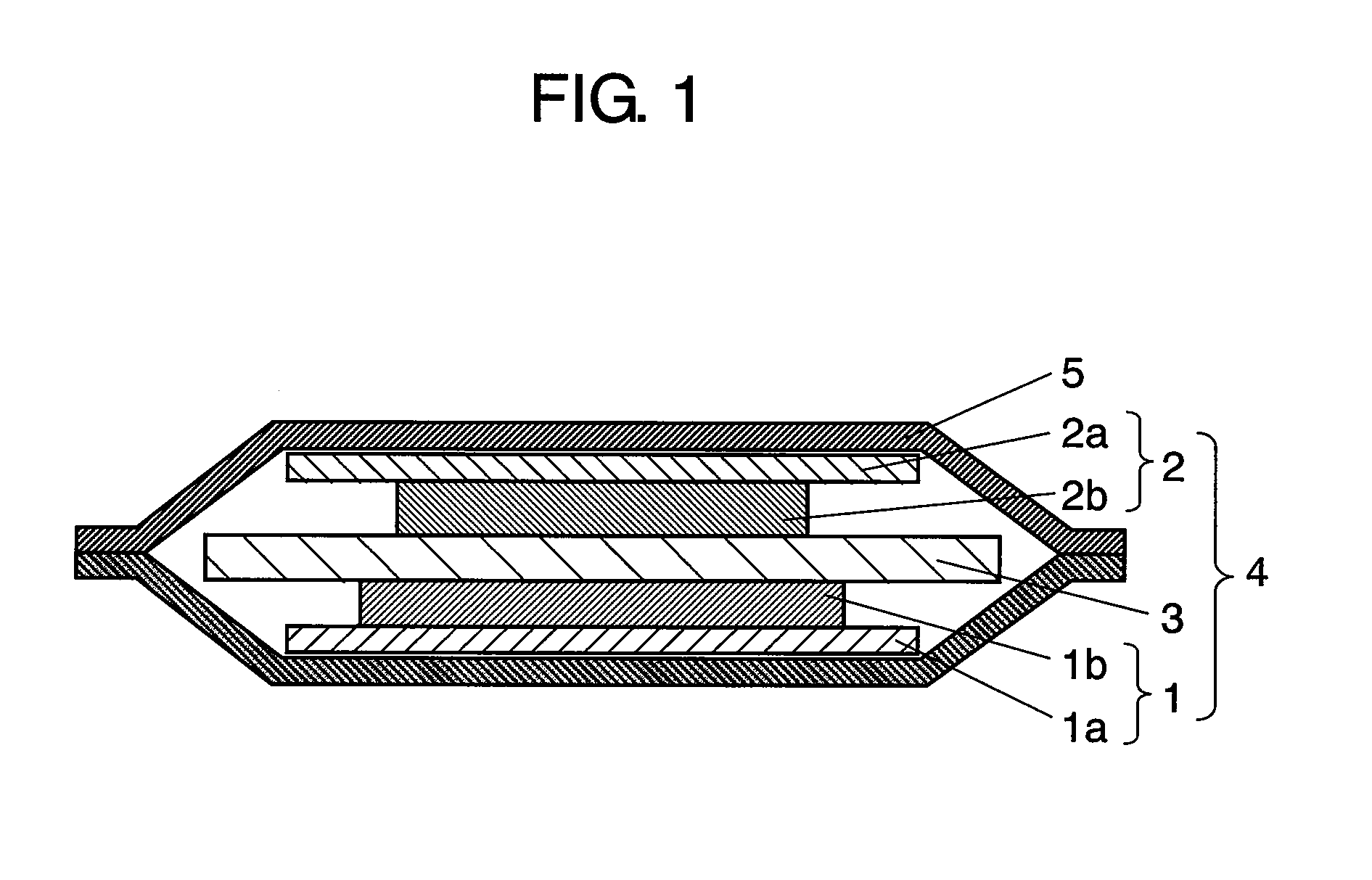
View PDF2 Cites 25 Cited by
  • Summary
  • Abstract
  • Description
  • Claims
  • Application Information

AI Technical Summary

Benefits of technology

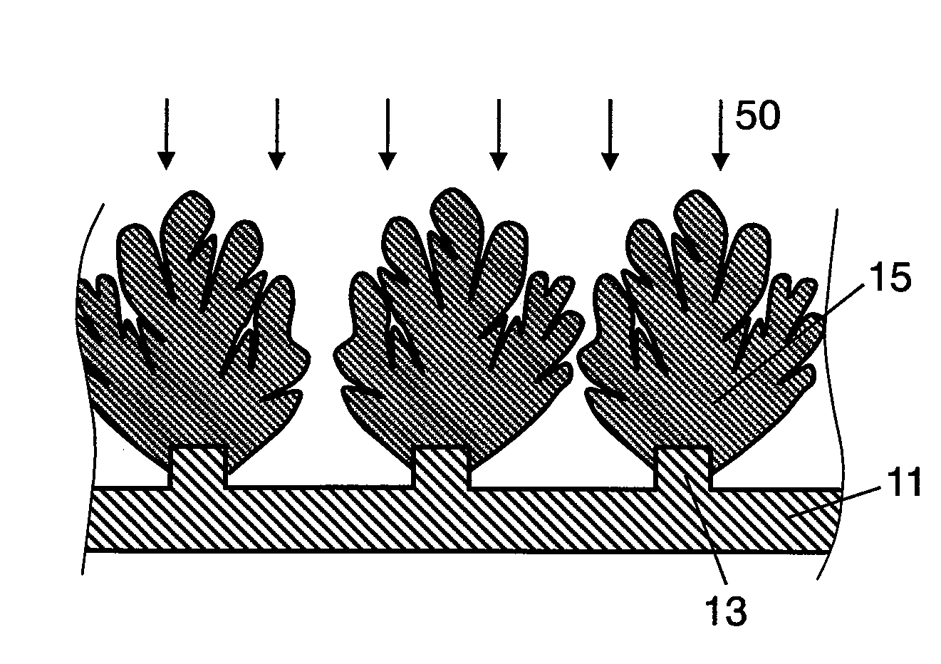
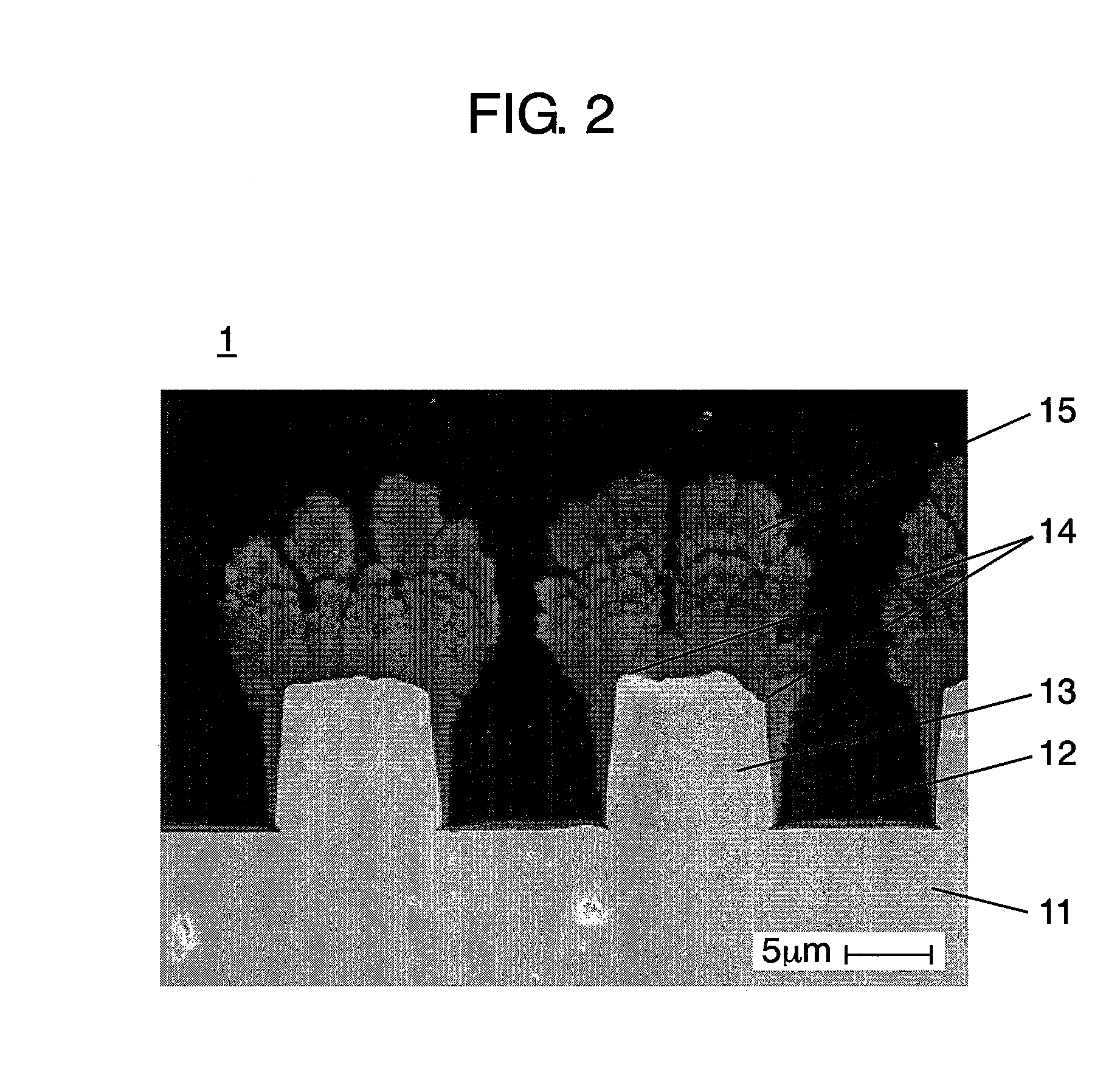
[0014]By this method, the columnar body is formed to cover a part of respective sides (surfaces) of the convex portion, and the junction strength is increased. As a result, an electrode for an electrochemical element of high capacity and excellent in charging and discharging cycle may be manufactured.

Problems solved by technology

As a result, the columnar negative electrode active materials mutually contact and press near the leading ends, and the current collector and the negative electrode active material may be peeled or the current collector may be wrinkled.
In addition, since the contact area of the convex portion of the current collector and the negative electrode active material is small, due to mutual contact of negative electrode active materials or insertion and extraction of lithium ions, the stress of expansion and contraction of negative electrode active material may be concentrated on the junction interface, and the characteristics are likely to decrease due to peeling or the like.
On the other hand, when the intervals of gaps are increased, since the negative electrode active material is columnar, the exposed surface area of the current collector is increased, and in the initial phase of charging, in particular, the lithium metal is likely to deposit, thereby causing decrease of safety and capacity.
Accordingly, prevention of occurrence of peeling of current collector and negative electrode active material or creasing of current collector, and advancement of capacity could not be satisfied at the same time.

Method used


Image

  • Manufacturing method of electrode for electrochemical element
  • Manufacturing method of electrode for electrochemical element
  • Manufacturing method of electrode for electrochemical element

Examples


first embodied example

[0087]First, the columnar body of the negative electrode was manufactured by using the RF plasma film forming device shown in FIG. 7.

[0088]On the surface of a current collector, by plating method, convex portions were formed by using a band-like electrolytic copper foil of 5 μm in height, 10 μm in width, 20 μm in interval, and 30 μm in thickness.

[0089]As an active material ingredient for the negative electrode, Si powder 75 at. % and SiO powder 25 at. % were used, and as carrier gas, a mixed gas of Ar / H2 was blended at a ratio of 50 (liters / min.) / 10 (liters / min.), and the both were supplied from the feed port of the torch. The supplied active material and carrier gas were gasified in plasma state by applying an RF electric power of 30 kW to the coil. The gasified active material in plasma state was injected toward the current collector placed at a position of 250 mm from the torch, and the columnar body grown radially was formed on the convex portion. This operation was done at inte...


PUM


Abstract

The invention presents a manufacturing method of an electrode for an electrochemical element for inserting and extracting a lithium ion reversibly, comprising; forming a concave portion and a convex portion at least on one side of a current collector, preparing a raw material containing a element for composing an active material, introducing a specified supply amount of the raw material and a carrier gas into a film forming device to form a plasma, and injecting the plasma of the raw material on the current collector, in which the active material is grown on the convex portion of the current collector, and a columnar body is formed by covering at least a part of respective sides of the convex portion.

Description

BACKGROUND OF THE INVENTION[0001]1. Field of the Invention[0002]The present invention relates to a manufacturing method of an electrode for an electrochemical element of high capacity and excellent in charging and discharging cycle characteristics[0003]2. Background Art[0004]Recently, a lithium ion secondary battery representing a nonaqueous electrolyte secondary battery is widely used, for example, as an electrochemical element because it is light in weight, high in electromotive force, and high in energy density. For example, as a driving power source for portable telephones, digital cameras, video cameras, laptop computers, and various portable electronic appliances and mobile communication devices or the like, the demand for the lithium ion secondary battery is increasing.[0005]The lithium ion secondary battery is composed of a positive electrode made of composite oxide containing lithium, a negative electrode containing lithium metal, lithium alloy, or negative electrode active...

Claims


Application Information

Patent Timeline
IPC IPC(8): H01M4/04H01G11/06H01G11/22H01G11/30H01G11/66H01G11/86H01M4/13H01M4/134H01M4/139H01M4/1395H01M4/36H01M4/38H01M4/48
CPCH01M4/0423H01M4/131H01M4/134H01M4/1391H01M4/1395H01M4/364H01M4/70H01M10/0525Y02E60/122Y02E60/10
Inventor OHTSUKA, TAKASHINAGATA, KAORUTAKEZAWA, HIDEHARUIMASHIKU, SHOICHI
Owner PANASONIC CORP
Learn More