
Method for sensing the liquid level in a compressor

a technology of liquid level and compressor, which is applied in the direction of positive displacement liquid engine, heat measurement, instruments, etc., can solve the problems of lag in fluid temperature, inaccurate representation of actual conditions of thermistor's electrical resistance, and sudden change in fluid conditions, etc., to achieve accurate factoring in rapid change of conditions inside the shell

Active Publication Date: 2008-10-16
TRANE INT INC
View PDF27 Cites 14 Cited by
  • Summary
  • Abstract
  • Description
  • Claims
  • Application Information

AI Technical Summary

Benefits of technology

[0008]It is an object of the invention to quickly and accurately determine the temperature of a fluid surrounding a thermistor that is alternately heated by electrical current and cooled by the fluid.
[0009]Another object of some embodiments is to quickly and accurately determine whether a thermistor is exposed to a liquid, gas or mixture of the two.
[0010]Another object of some embodiments is to provide an alternative to identifying a time constant for a thermistor, thereby avoiding processor time normally spent on calculating exponents of natural log functions or accessing exponential lookup tables.

Problems solved by technology

Unfortunately, however, the thermistor's temperature lags a fluid's changing temperature due to a limited heat transfer rate between the thermistor and the surrounding fluid.
When this technology, for example, is used in a conventional manner to sense the oil / refrigerant fluid conditions within the sump of a refrigerant compressor, the fluid conditions can change so suddenly that the thermistor's electrical resistance might inaccurately represent the actual conditions within the sump.
As a result, the thermistors might fail to detect a fluid related problem.
At startup, for instance, a refrigerant compressor might experience a rapid loss of oil due to excessive foaming within the compressor's sump.
Such foaming can be caused by a suction line blockage, closed expansion valve, closed service valve, or some other problem.
Thus, the compressor might ingest the foamy mixture, creating a liquid slugging problem, and discharge the mixture, thereby losing oil that is needed for ongoing compressor operation.
Although various types of sensors might be used for detecting such problems, conventional sensors with existing control schemes can be too slow to react in time to protect the compressor, and faster control schemes can be too expensive.

Method used


Image

  • Method for sensing the liquid level in a compressor
  • Method for sensing the liquid level in a compressor
  • Method for sensing the liquid level in a compressor

Examples


Embodiment Construction

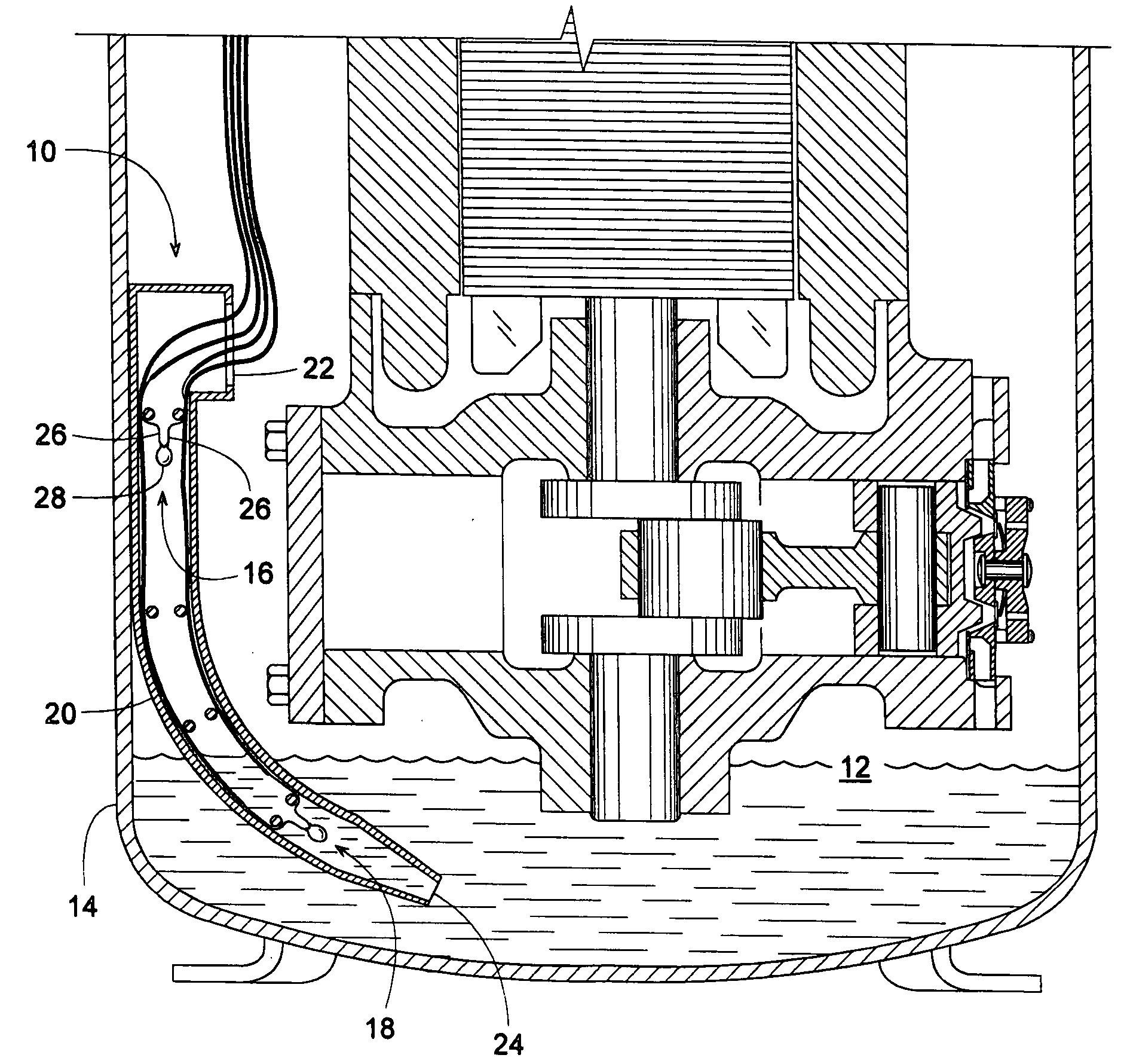
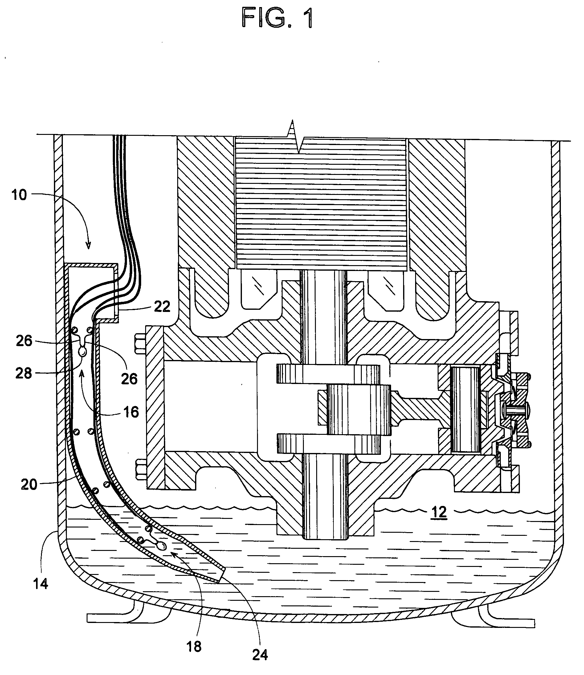
[0028]FIG. 1 shows a device 10 for sensing a fluid 12, such as oil and / or refrigerant within a hermetically sealed compressor shell 14. Although FIG. 1 shows a reciprocating compressor, other types of compressors, preferably scroll compressors but also other compressors such as screw or centrifugal, are well within the scope of the invention. Regardless of the type of compressor, device 10 can determine the fluid's sump temperature, high / low liquid levels, and determine whether it is sensing fluid 12 as a liquid, gas, or a mixture of the two, such as a foam or mist of gas and liquid. The compressor's sump temperature is the temperature of fluid 12 preferably in liquid form at the bottom of shell 14.

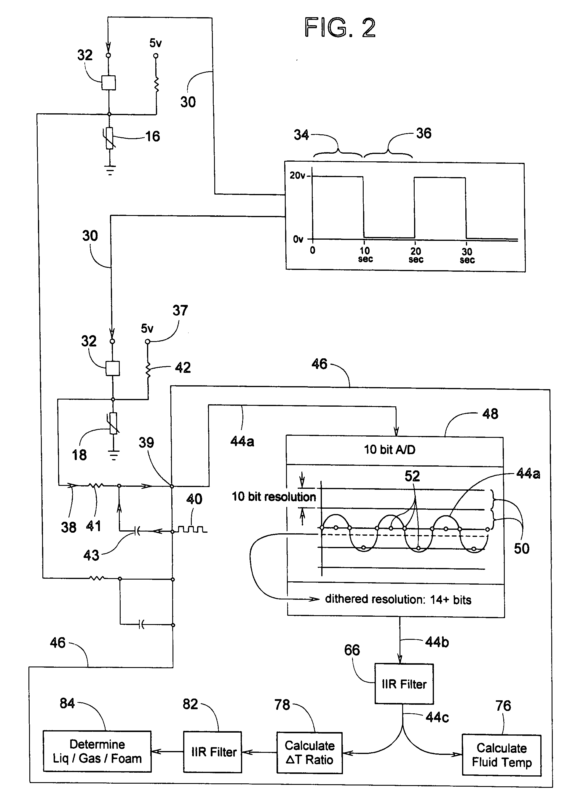
[0029]Since fluidic and thermodynamic conditions can change so rapidly within compressor shell 14, device 10 needs to be extremely accurate and have an exceptionally fast response time. To accomplish this with relatively inexpensive sensors and an affordable microprocessor, several hardwa...


PUM


Abstract

Two vertically offset thermistors for sensing a fluid such as oil and refrigerant in a compressor shell are monitored by a method that takes into account rapidly changing conditions within the shell. The system can determine the fluid's sump temperature, high / low liquid levels, and can determine whether the thermistors are sensing the fluid as a liquid, gas, or a mixture of the two, such as a foam or mist of liquid and gas. For greater accuracy, thermistor readings can be dithered and filtered to provide temperature or voltage values having more significant digits than the readings originally processed through a limited-bit A / D converter. For faster response, limited microprocessor time is conserved by sampling thermistor readings at strategic periods that enable the microprocessor to identify certain conditions and temperatures via simple delta-temperature ratios and undemanding equations rather than resorting to exponential functions or lookup tables to determine time constants.

Description

FIELD OF THE INVENTION[0001]The subject invention generally pertains to a device and method for sensing the liquid level and temperature of a fluid in a compressor and more specifically to a method that can distinguish whether a sensor is detecting a liquid, gas or foam.BACKGROUND OF RELATED ART[0002]A thermistor's electrical resistance changes as a function of its temperature, which is the basic principle that enables thermistors to be used for sensing fluid temperatures or liquid levels.[0003]For example, to sense whether a liquid level has reached a certain upper limit, a thermistor with a positive or negative temperature coefficient can be energized to electrically heat the thermistor to a temperature above that of the liquid. Then, if the liquid level is below the thermistor, the relatively low heat transfer rate between the electrically heated thermistor and the gas above the liquid allows the thermistor's temperature to remain elevated. If, however, the liquid level rises to ...

Claims


Application Information

Patent Timeline
IPC IPC(8): F04B39/02G01K13/00
CPCF04B39/02F04B39/0207G01F23/247G01K1/16G01K3/10
Inventor OKOREN, RONALD W.BROWN, JERRY E.VANDERZEE, JOEL C.NELSON, CHARLES E.KLINGEMANN, STEVEN K.DEGROOT, JEFFREY J.
Owner TRANE INT INC
Learn More