Liquid crystal display and display control method for the same

a technology of liquid crystal display and control method, applied in the direction of display means, illuminated signs, instruments, etc., can solve the problems of image quality degradation such as a decline in the brightness of an image, and the value of backlight lighting time in the screen region, so as to reduce the discomfort associated with switching, reduce the number of parts, and reduce the effect of power consumption of partial screen display

Active Publication Date: 2008-10-16
SATURN LICENSING LLC
View PDF5 Cites 21 Cited by
  • Summary
  • Abstract
  • Description
  • Claims
  • Application Information

AI Technical Summary

Benefits of technology

[0015]In the display and the display control method for a display according to the embodiment of the invention, the light emission state of the backlight arranged corresponding to each of the sub regions is monitored, and a sub region on which an image is to be displayed is determined on the basis of the monitoring result, and the image is fitted into the determined sub region, and a backlight corresponding to the determined sub region emits light, so when partial drive display on the display panel is performed, the light emission characteristics of the backlight is able to be controlled so as to be uniform on the full screen. As a result, the power consumption by partial screen display may be reduced without time degradation in image quality.
[0016]In particular, in the case where the cumulative light emission time of the backlight for each of the sub regions is monitored as a mode of monitoring the light emission state by the monitoring means, time degradation in the backlight for each of the sub regions is able to be indirectly detected through the use of the cumulative light emission time. In this case, it is not necessary to specifically arrange a brightness sensor, so an increase in the number of parts may be prevented.
[0017]Moreover, in the case where a display switching operation from the current sub region to another sub region is performed in synchronization with an operation to the input section, the sense of discomfort associated with switching may be reduced.

Problems solved by technology

However, in this method, the cumulative value of the backlight lighting time in a screen region used for displaying the downsized image is different from that in the other screen region.
As a result, light emission characteristics of a backlight for a region where the lighting time is long decline over time, compared to a backlight for a region where the lighting time is short, so degradation in image quality such as a decline in the brightness of an image or color unevenness occurs accordingly.

Method used


Image

  • Liquid crystal display and display control method for the same
  • Liquid crystal display and display control method for the same
  • Liquid crystal display and display control method for the same

Examples


Embodiment Construction

[0025]A best mode for carrying out the invention (hereinafter simply referred to embodiment) will be described in detail below referring to the accompanying drawings.

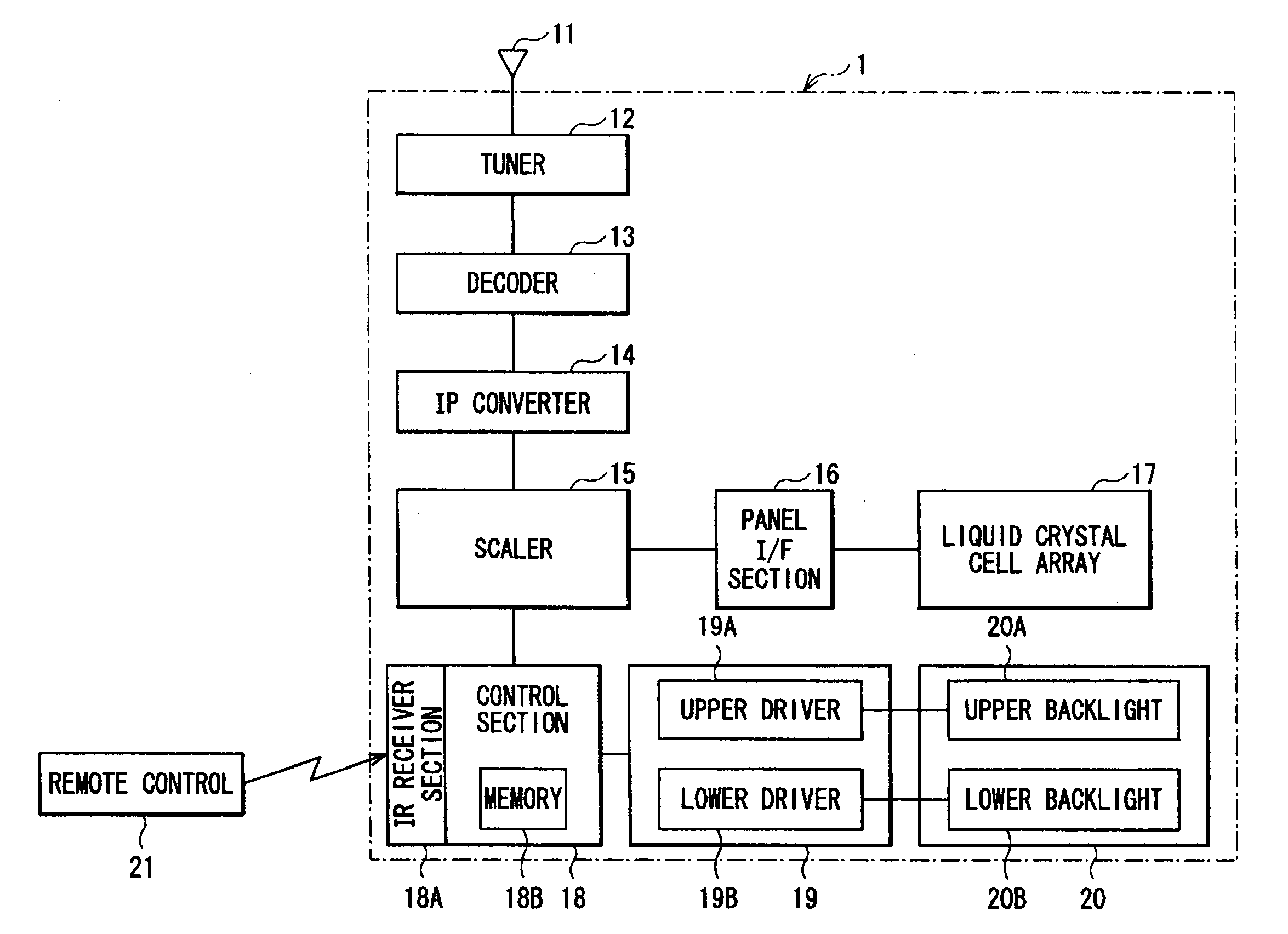
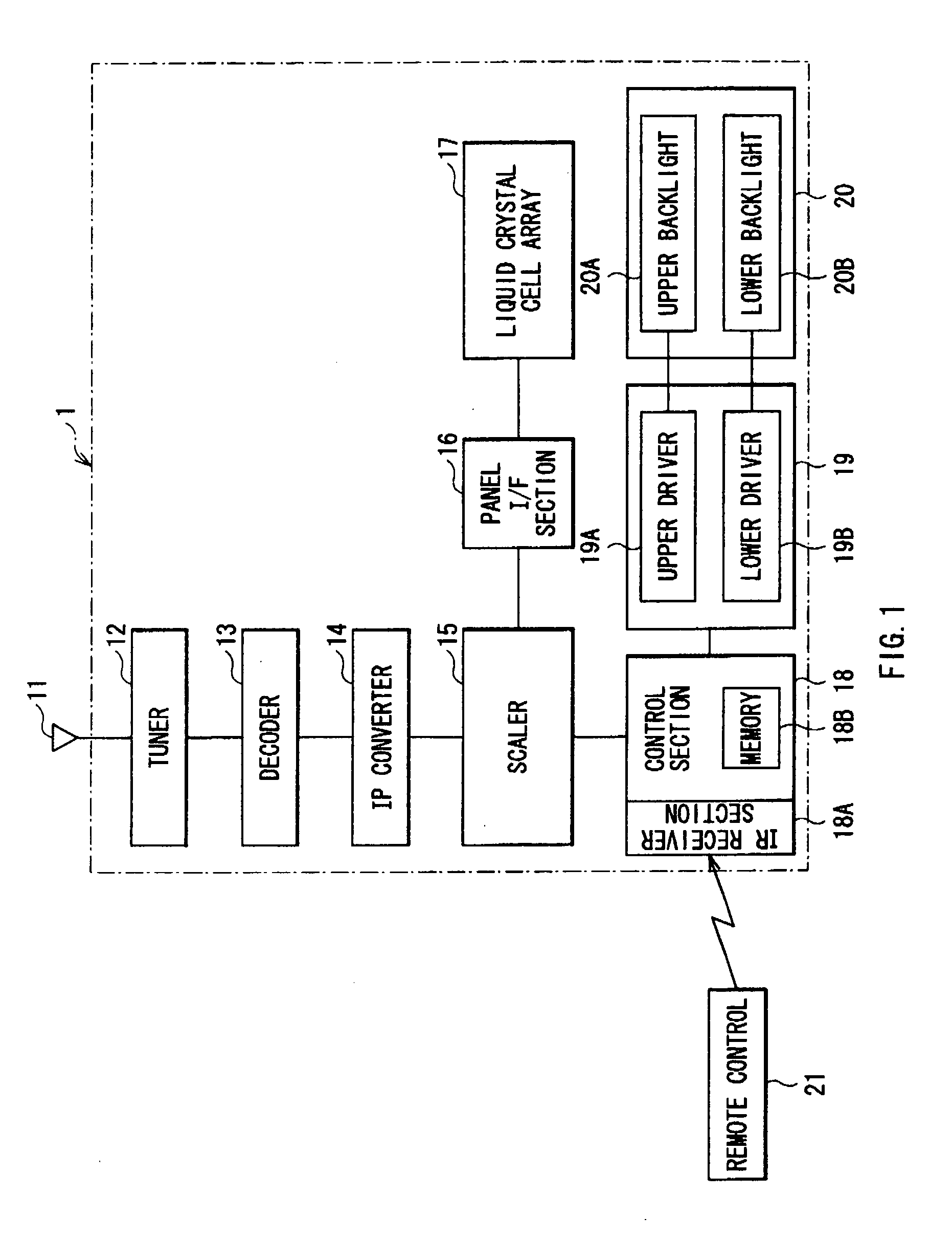
[0026]FIG. 1 schematically shows the configuration of a liquid crystal display according to an embodiment of the invention. A liquid crystal display 1 is configured as a television receiver, and includes a tuner 12 for channel tuning which is connected to an image receiving antenna 11, a decoder 13 connected to the tuner 12, and an IP converter 14 connected to the decoder 13. The decoder 13 decodes an encoded signal selected by the tuner 12 to capture a video signal, an audio signal and associated data. The IP converter 14 converts the video signal which is an interlaced signal into a progressive signal (a non-interlaced signal).

[0027]The liquid crystal display 1 further includes a scaler 15 connected to the IP converter 14, a panel interface (I / F) section 16 connected to the scaler 15, and a liquid crystal cell array 1...


PUM

PropertyMeasurementUnit
light emission timeaaaaaaaaaa
cumulative light emission timeaaaaaaaaaa
currentaaaaaaaaaa

Abstract

In the case where a screen divided display is performed on a liquid crystal panel, a change in brightness or chromaticity between sub regions divided may be reduced. A display includes: a display panel; a backlight arranged corresponding to each of sub regions, and selectively illuminating the corresponding sub region, the sub regions being defined by dividing a display region of the display panel into a plurality of parts; a monitoring means for monitoring the light emission state of the backlight corresponding to each of the sub regions; and a display control means for determining a sub region on which an image is to be displayed, on the basis of the monitoring result of the monitoring means, to fit the image into the determined sub region, and controlling a backlight corresponding to the determined sub region to emit light.

Description

CROSS REFERENCES TO RELATED APPLICATIONS[0001]The present invention contains subject matter related to Japanese Patent Application JP 2007-104018 filed in the Japanese Patent Office on Apr. 11, 2007, the entire contents of which being incorporated herein by reference.BACKGROUND OF THE INVENTION[0002]1. Field of the Invention[0003]The present invention relates to a liquid crystal display displaying an image on a liquid crystal panel through the use of a backlight, and a display control method for the liquid crystal display.[0004]2. Description of the Related Art[0005]Large-screen liquid crystal televisions has steadily become popular at home according to advances in liquid crystal panel technology and cost reduction. In particular, in the case of watching a program such as a movie program or a sports program, a higher level of realism may be obtained with such a large-screen liquid crystal television. On the other hand, there is an issue that such a large-screen television consumes a...

Claims


Application Information

Patent Timeline
Patent Type & Authority Applications(United States)
IPC IPC(8): G09G3/36G02F1/13357G02F1/133G09G3/20G09G3/34
CPCG02F2001/133601G02F2001/133612G09G3/342G09G2320/043G09G2320/048G09G2320/062G09G2320/0626G09G2330/021G09G2340/0407G02F1/133601G02F1/133612G01J1/42G02F1/133G09G3/20G09G3/36
Inventor DOI, HIROSHI
Owner SATURN LICENSING LLC
Why Eureka
Try Eureka