Substrate processing apparatus and substrate processing method

Inactive Publication Date: 2008-10-16
DAINIPPON SCREEN MTG CO LTD
View PDF7 Cites 9 Cited by
  • Summary
  • Abstract
  • Description
  • Claims
  • Application Information

AI Technical Summary

Benefits of technology

[0008]The invention has been made in light of the problem described above and accordingly an object of the invention is to provide a substrate processing apparatus and a substrate processing method, capable of processing the top rim portion of the substrate excellently without receiving negative impact of droplets of the processing liquid by discharging the droplets which have adhered from the top rim portion of the substrate to the nozzle insertion hole from the nozzle insertion hole.

Problems solved by technology

Furthermore, depending on the type of processing liquid, some droplets may turn into solid, which become a cause of particle contamination.

Method used


Image

  • Substrate processing apparatus and substrate processing method
  • Substrate processing apparatus and substrate processing method
  • Substrate processing apparatus and substrate processing method

Examples


first embodiment

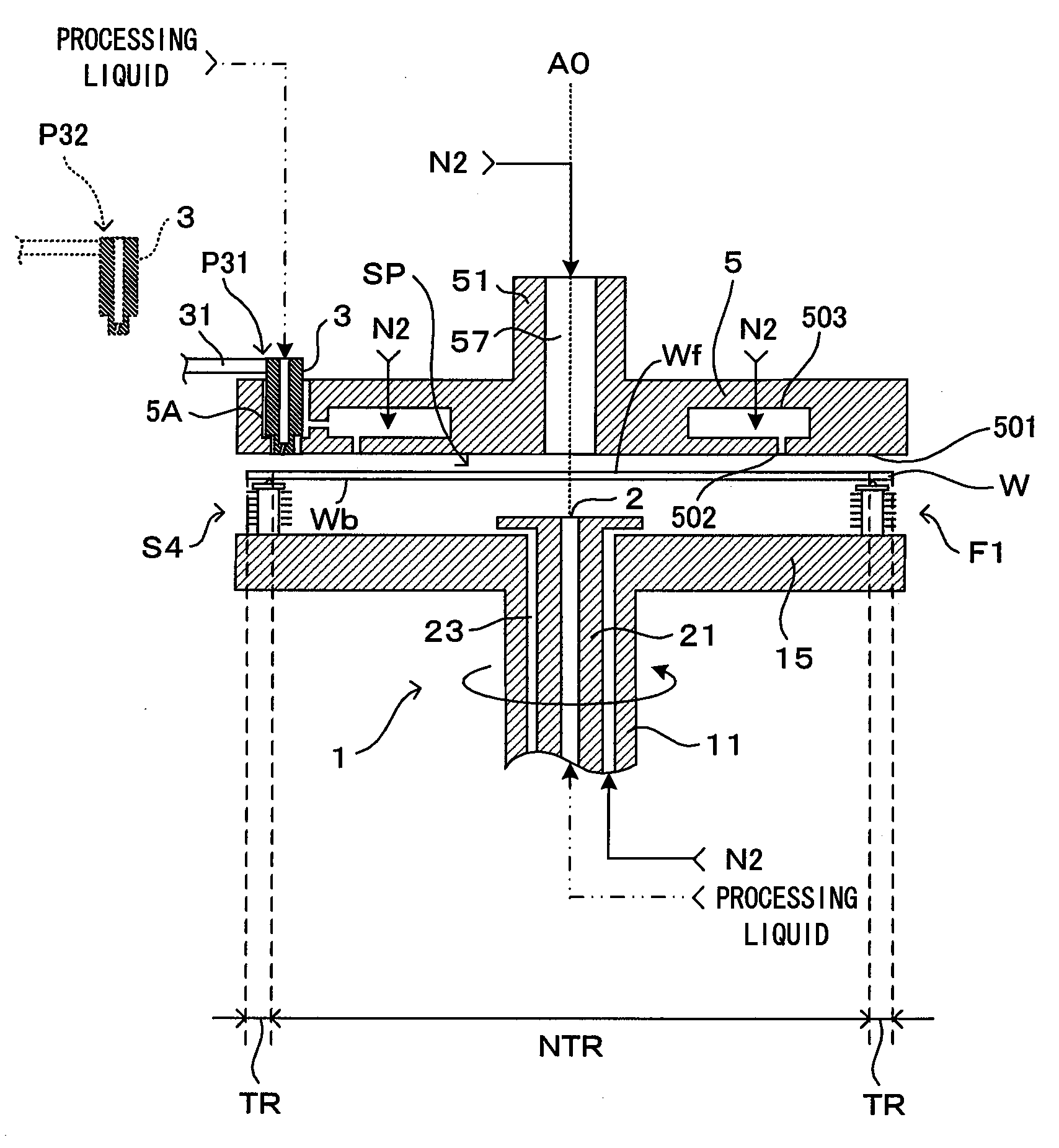
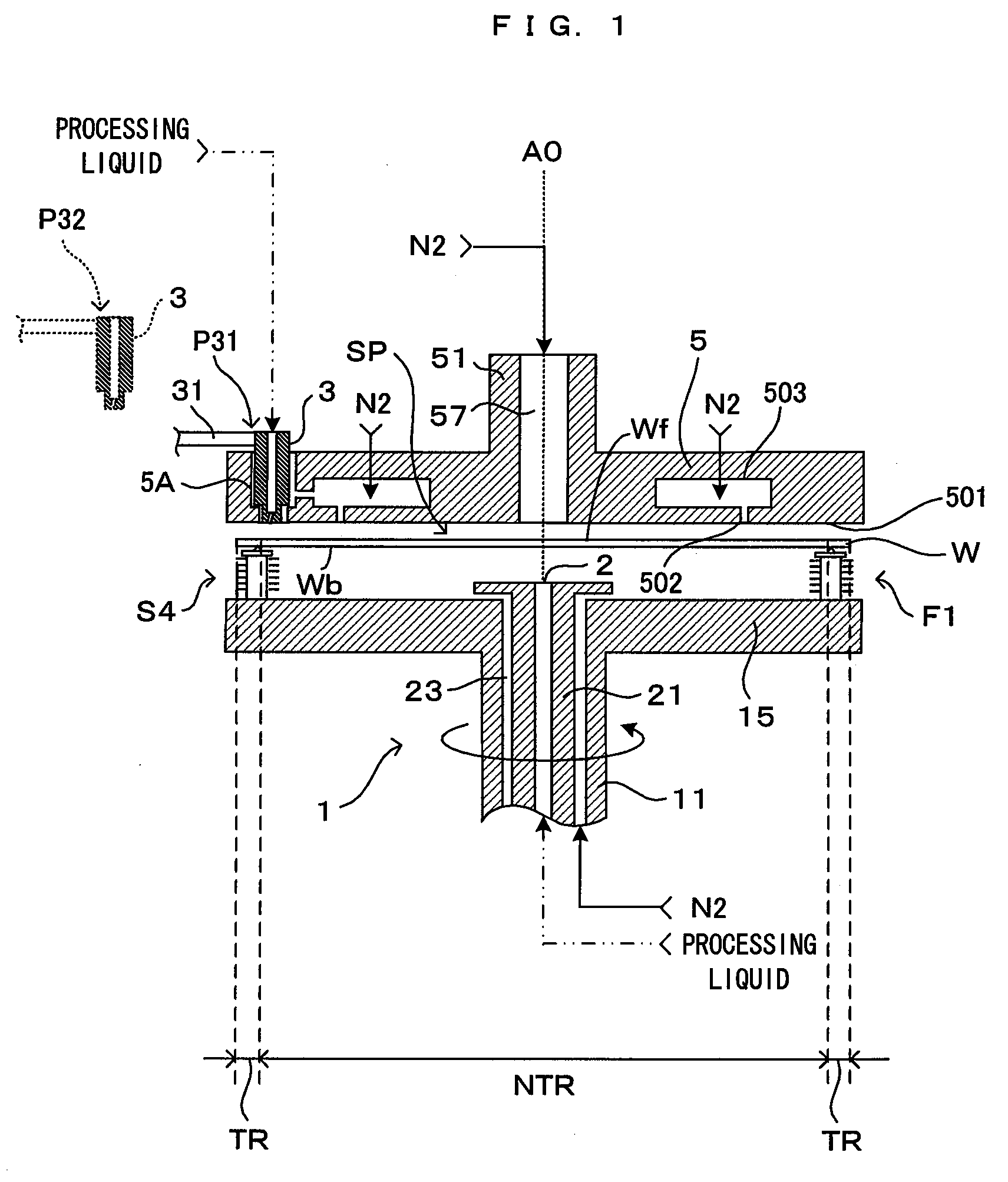
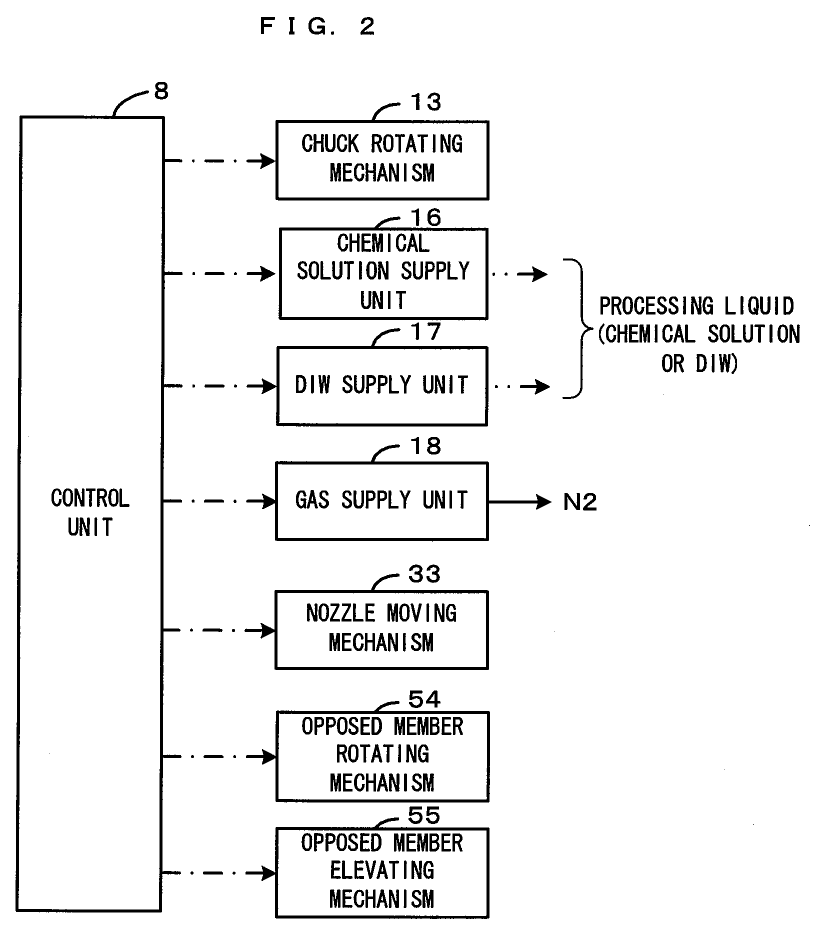
[0024]FIG. 1 is a diagram showing a first embodiment of a substrate processing apparatus according to the invention. FIG. 2 is a block diagram showing a main control configuration of the substrate processing apparatus which is shown in FIG. 1. This substrate processing apparatus is an apparatus which cleans a rim portion of a top surface Wf of an approximately circular substrate W such as a semiconductor wafer, specifically an apparatus which removes by etching a thin film (undesired substance) which is present on the rim portion of the top surface Wf of the substrate W or is present both on the rim portion and on a substrate rear surface Wb. The substrates W to be processed include a substrate on the substrate surface Wf of which a this film which is hardly soluble in the chemical solution such as a SiN film or high-k film is formed, and a substrate W on the top surface Wf and the rear surface Wb of which the above thin film is formed. Consequently, in the case where the thin film ...

second embodiment

[0062]FIGS. 9 and 10 are diagrams showing a second embodiment of a substrate processing apparatus according to this invention. FIG. 9 is a lower surface view of the opposed member from the substrate, and FIG. 10 is a partial perspective view showing a nozzle and a nozzle insertion hole. A major difference of the substrate processing apparatus according to the second embodiment from the first embodiment is that a groove part 533 is additionally formed as the guide portion 53 near the opening of the nozzle insertion hole 52. The other structure is the same as that according to the first embodiment. Therefore, the description herein is focused on the differences, and the same structure will be denoted at the same reference symbols but will not be described.

[0063]In this second embodiment, the groove part 533 is provided near a part (corresponding to the enlarged part 531 in the partial enlarged view in FIG. 5A) of the opening 521 located in the liquid discharging direction X relative t...


PUM

PropertyMeasurementUnit
diameteraaaaaaaaaa
forcesaaaaaaaaaa
rotationaaaaaaaaaa

Abstract

A part of the opening of the nozzle insertion hole located in the liquid discharging direction relative to the nozzle inserted in the nozzle insertion hole is enlarged in the liquid discharging direction. Therefore, the droplets which have migrated to the nozzle insertion hole adheres to the internal surface in the liquid discharging direction relative to the nozzle, that is, to the slanted part via the enlarged part. Moreover, the slanted part is provided slanted from the central portion of the nozzle insertion hole toward the enlarged part and separated away from the central portion of the substrate top surface. Hence, the adhering droplets flow in the liquid discharging direction along the slanted part to be discharged from the opening of the nozzle insertion hole.

Description

CROSS REFERENCE TO RELATED APPLICATION[0001]The disclosure of Japanese Patent Application No. 2007-020743 filed Jan. 31, 2007 including specification, drawings and claims is incorporated herein by reference in its entirety.BACKGROUND OF THE INVENTION[0002]1. Field of the Invention[0003]The present invention relates to a substrate processing apparatus and a substrate processing method which supplies a processing liquid to a top rim portion of a substrate to thereby perform a predetermined surface processing to the top rim portion, the substrate including semiconductor wafers, glass substrates for photomask, glass substrates for liquid crystal display, glass substrates for plasma display, substrates for FED (field emission display), substrates for optical disks, substrates for magnetic disks, substrates for magnet-optical disks, etc.[0004]2. Description of the Related Art[0005]In a production process in which a series of processing is performed to the substrates such as semiconductor ...

Claims


Application Information

Patent Timeline
Patent Type & Authority Applications(United States)
IPC IPC(8): B05D1/02B05B13/02
CPCH01L21/6708H01L21/6875Y10S134/902H01L21/304H01L21/306
Inventor KISHIMOTO, TAKUYAMIYA, KATSUHIKO
Owner DAINIPPON SCREEN MTG CO LTD
Why Eureka
Try Eureka