Electrophoretic media and displays with improved binder

a technology of electrophoretic media and binder, which is applied in the direction of electrolysis components, instruments, cells, etc., can solve the problems of gas-based electrophoretic media being susceptible to the same types of problems, preventing their widespread use, and inadequate service life of these displays

Inactive Publication Date: 2007-04-26
E INK CORPORATION
View PDF99 Cites 152 Cited by
  • Summary
  • Abstract
  • Description
  • Claims
  • Application Information

AI Technical Summary

Problems solved by technology

Nevertheless, problems with the long-term image quality of these displays have prevented their widespread usage.
For example, particles that make up electrophoretic displays tend to settle, resulting in inadequate service-life for these displays.
Such gas-based electrophoretic media appear to be susceptible to the same types of problems due to particle settling as liquid-based electrophoretic media, when the media are used in an orientation which permits such settling, for example in a sign where the medium is disposed in a vertical plane.
Indeed, particle settling appears to be a more serious problem in gas-based electrophoretic media than in liquid-based ones, since the lower viscosity of gaseous suspending fluids as compared with liquid ones allows more rapid settling of the electrophoretic particles.
Obviously, it is desirable to keep DTD as small as possible since DTD affects the difficulty of driving the display and may affect the quality of the image produced; for example, DTD may cause pixels which are supposed to form an area of uniform gray color to differ slightly from one another in gray level, and the human eye is very sensitive to such variations.
Although it has been known that the choice of binder affects DTD, choosing an appropriate binder for any specific electrophoretic medium has hitherto been based on trial-and-error, with essentially no understanding of the relationship between DTD and the chemical nature of the binder.
Choosing a binder which satisfies all the relevant requirements for use in such displays is not easy, and in practice only a limited number of commercial materials are suitable.

Method used


Image

  • Electrophoretic media and displays with improved binder
  • Electrophoretic media and displays with improved binder
  • Electrophoretic media and displays with improved binder

Examples


example 1

Synthesis of Polyurethanes

[0034] The reactants used in the experiments were as follows:

[0035] H12MDI (IUPAC name bis(4-isocyanatocyclohexyl)methane)

[0036] Five different polyurethanes were used in these experiments, as set out In Table 1 below:

TABLE 1Poly-Solids,urethaneDiisocyanateDiolMwpHwt. %AH12MDIPPO641007.740BTMXDIPPO387008.440CTMXDIPCL297007.634DTMXDIPPO45000-550007.5-8.535EH12MDIPolyester 100-200K7.5-8.540

[0037] Polyurethanes A, B and C were formulated to have the same molar ratios of diol to diisocyanate; Polyurethane D is a custom polyurethane prepared by a third party in accordance with U.S. Patent Publication No. 2005 / 0124751, while Binder E was also a commercial polyurethane.

[0038] The synthesis of Polyurethane A was carried out under nitrogen as follows. A jacketed 500 mL glass reactor was equipped with a mechanical stirrer, a thermometer, and a nitrogen inlet. H12MDI (20.99 g of Bayer Desmodur W, 0.08 mole), poly(propylene glycol) diol (50 g, supplied by Aldri...

example 2

Electro-Optic Properties

[0042] In order to evaluate the effect of the various polyurethane binders on the electro-optic properties of electrophoretic displays, electrophoretic capsules comprising an internal phase containing carbon black and titania electrophoretic particles in a hydrocarbon fluid, surrounded by a capsule wall formed from a gelatin / acacia coacervate, were prepared substantially as described in U.S. Patent Publication No. 2002 / 0180687, Paragraphs [0067] to [0072]. The resultant capsules were mixed with the binders and binder blends specified below and formed into experimental single pixel displays substantially as described in Paragraphs [0073] and [0074] of this Publication, except that a backplane comprising a carbon black electrode on a polymer film was used. The lamination adhesive used was Binder D doped with 180 parts per million of tetrabutylammonium hexafluorophosphate (cf. the aforementioned U.S. Pat. No. 7,012,735).

[0043] The resultant experimental displa...

example 3

Effect of Binder Composition on DTD

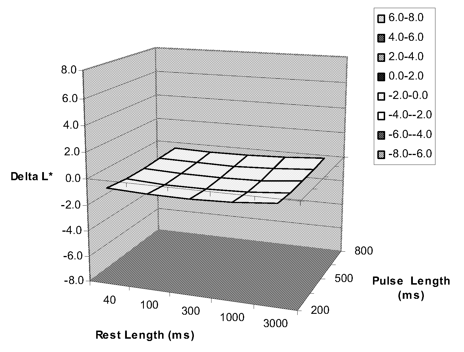
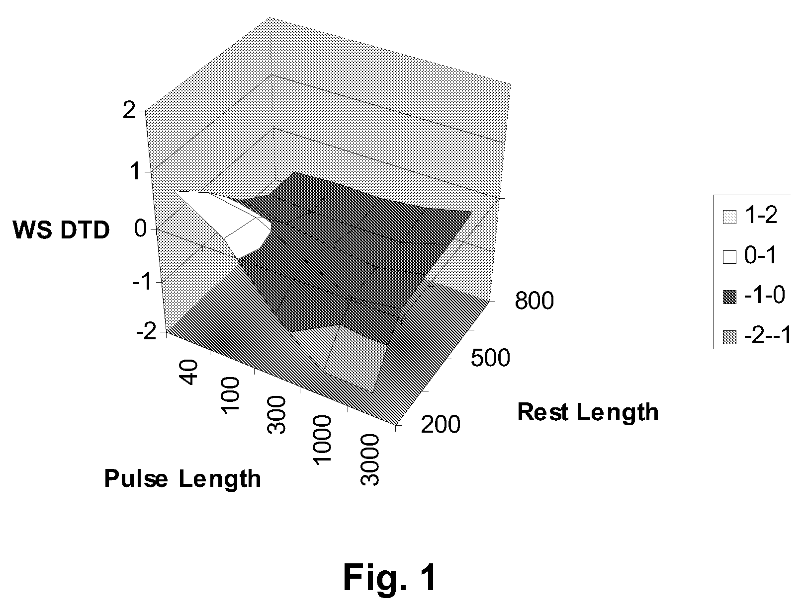
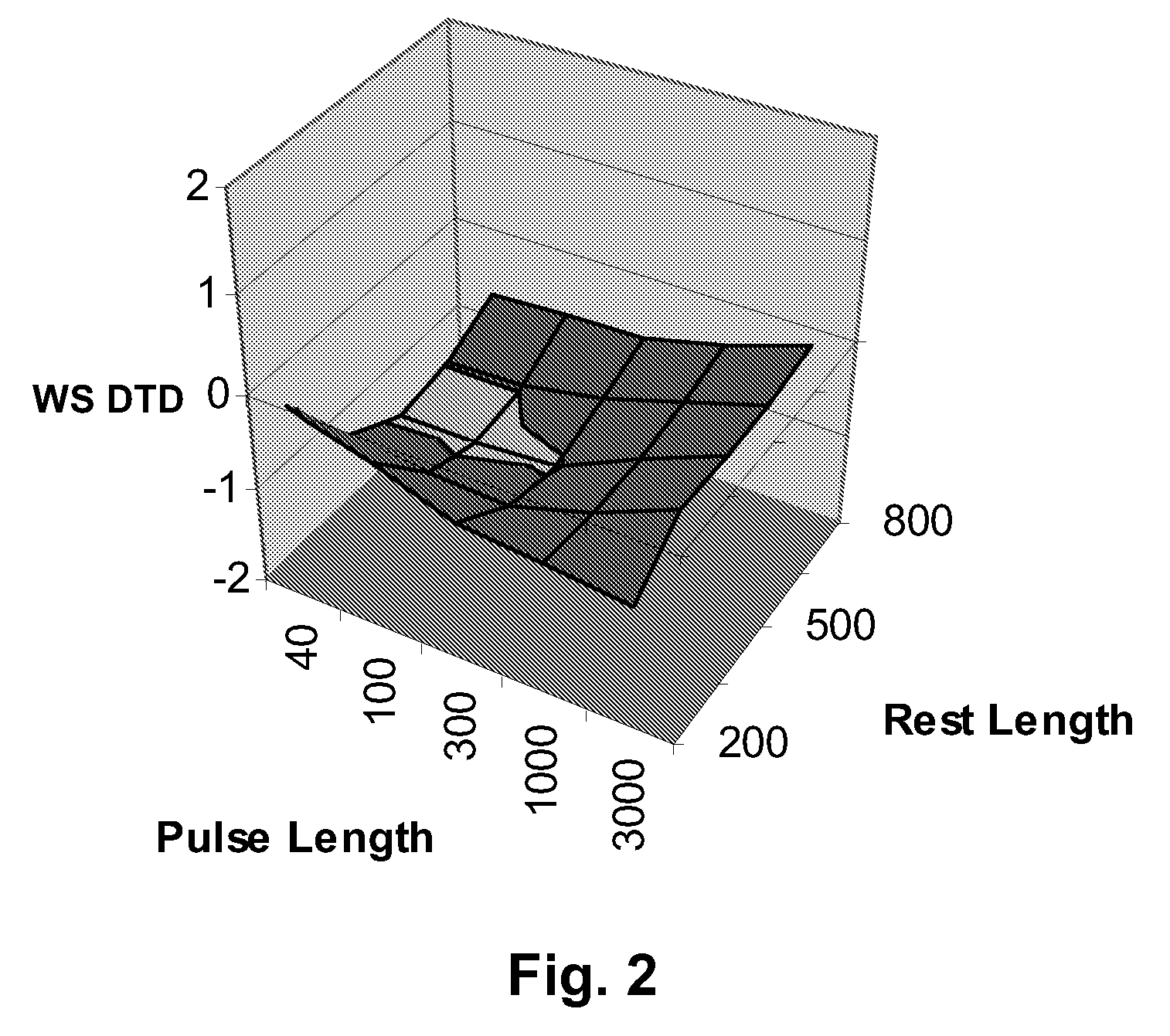
[0047] The experiments used to generate the graph shown in FIG. 1 were repeated with the same capsules but using as the binder Polyurethane D from Table 1 above. The results are shown in FIG. 2.

[0048]FIG. 2 shows substantial reduction in DTD compared with FIG. 1; the overall Max-Min range is reduced from 2.4 L* to 1.2 L*, and the sign of the DTD is generally opposite to that in FIG. 1, thus implying that the electrophoretic particles were experiencing a smaller voltage than that actually applied between the electrodes.

[0049] The experiments which produced the graphs of FIGS. 1 and 2 were repeated several times using the same binders but different types of capsules. Although the values of the DTD range varied considerably with the specific type of capsules used (varying from 3.4 to 7.2 L* units for the FIG. 1 binder and from 0.6 to 4.7 L* for Polyurethane D), in every case the Polyurethane D binder showed a lower DTD range than the FIG. 1 binder....


PUM

PropertyMeasurementUnit
temperatureaaaaaaaaaa

Abstract

An electrophoretic medium comprises discrete droplets of an electrophoretic internal phase comprising a fluid and carbon black particles in the fluid. The droplets are surrounded by a polyurethane binder formed by a diisocyanate and a polyether diol, at least 20 mole per cent of the diisocyanate being an aromatic diisocyanate.

Description

REFERENCE TO RELATED APPLICATIONS [0001] This application claims benefit of copending Application Ser. No. 60 / 596,836, filed Oct. 25, 2005. [0002] This application is related to: [0003] (a) U.S. Pat. No. 7,110,164; [0004] (b) U.S. Pat. No. 6,982,178; [0005] (c) U.S. Pat. No. 6,831,769; and [0006] (d) U.S. Pat. No. 7,119,772. [0007] The entire contents of this copending application and patents, and of all other U.S. patents and published and copending applications mentioned below, are herein incorporated by reference.BACKGROUND OF INVENTION [0008] The present invention relates to electrophoretic media and displays with an improved binder. More specifically, this invention relates to electrophoretic media and displays with a binder which reduces dwell time dependence. [0009] The terms “bistable” and “bistability” are used herein in their conventional meaning in the art to refer to displays comprising display elements having first and second display states differing in at least one opt...

Claims


Application Information

Patent Timeline
Patent Type & Authority Applications(United States)
IPC IPC(8): G02B26/00C25B9/17G02F1/167
CPCG02B26/026G02F1/167G02F2001/1678
Inventor CAO, LANGATES, ELIZABETH M.MILLER, DAVID D.DANNER, GUY M.PAOLINI, RICHARD J. JR.
Owner E INK CORPORATION
Why Eureka
Try Eureka