Endoscope with Miniature Imaging Arrangement

a miniature imaging and endoscope technology, applied in the field of endoscopes, can solve the problems of uneven light distribution, color imbalance between different parts of the image, and inability to get an image that is free of saturation and at the same time clearly showing the dark elements of the scen

Inactive Publication Date: 2008-10-16
SUPER DIMENSION
View PDF9 Cites 86 Cited by
  • Summary
  • Abstract
  • Description
  • Claims
  • Application Information

AI Technical Summary

Benefits of technology

[0013]According to a further feature of the present invention, there is also provided: (a) at least one light source for illuminating the scene viewed from the distal tip portion; and (b) an optically dispersive medium distally overlying the light source such that the optically dispersive medium is effective to disperse illumination from the light source, thereby illuminating the scene viewed from the distal tip portion, without obscuring light reflected from the scene from reaching the lens arrangement.

Problems solved by technology

Practically, since the dynamic range of the sensor is finite, in a wide viewing angle, where very close and very far tissues are seen in the same exposure, it is impossible to get an image that is free of saturation and at the same time clearly shows the dark elements of the scene.
The incorporation of light sources into the distal tip of a very miniature endoscope often presents problems of uneven light distribution.
In particular, where different colors of illuminating light are supplied from different light emitting diodes (LEDs), or via separate optic fibers from an external source, the differing geometrical positions of the light sources for the different colors often causes color imbalance between different parts of the image.
A further problem in very miniature systems is the proximity of the light source to the image detector array which may lead to light leakage between the lens arrangement and the image sensor array.

Method used


Image

  • Endoscope with Miniature Imaging Arrangement
  • Endoscope with Miniature Imaging Arrangement
  • Endoscope with Miniature Imaging Arrangement

Examples


Embodiment Construction

[0045]The present invention is an endoscope with a miniature imaging arrangement.

[0046]The principles and operation of endoscopes according to the present invention may be better understood with reference to the drawings and the accompanying description.

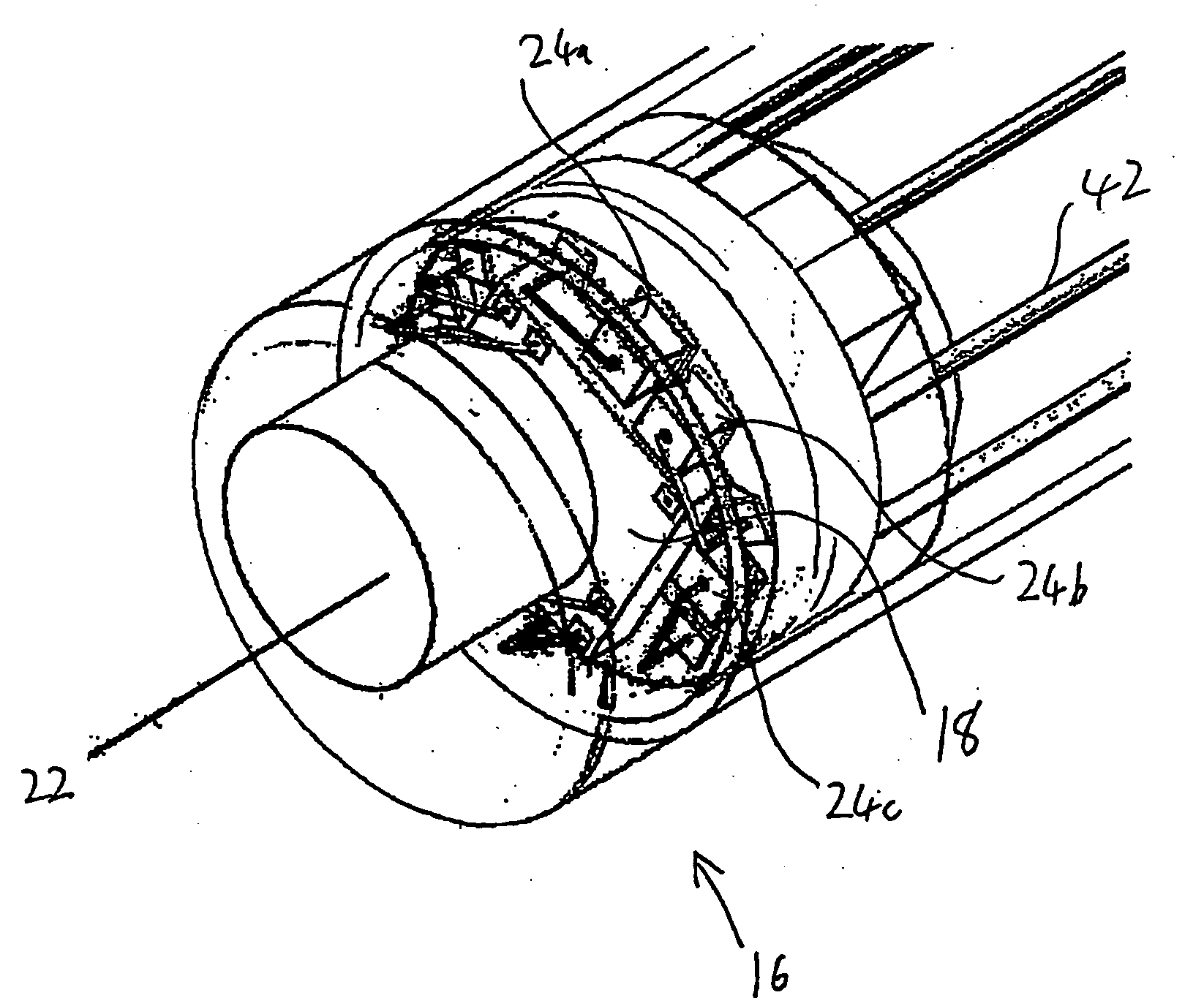
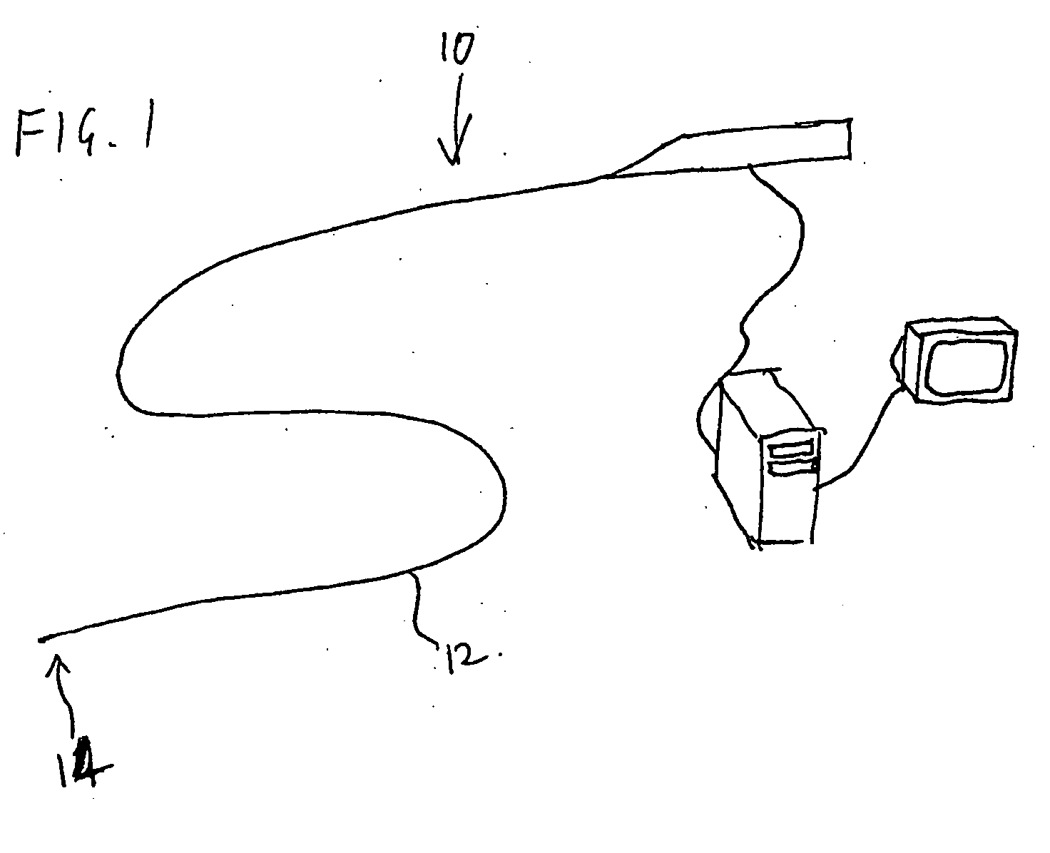
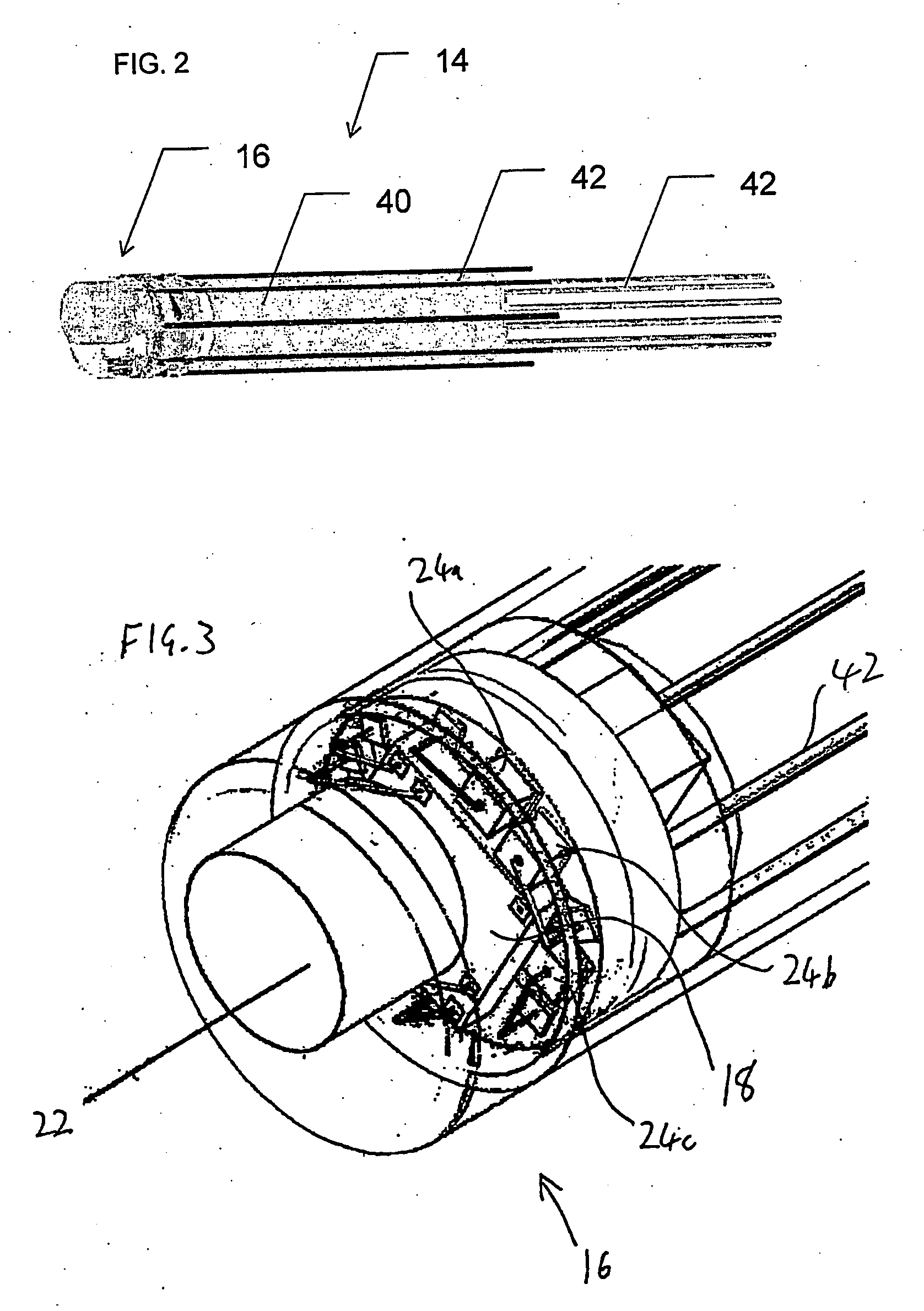
[0047]Referring now to the drawings, FIG. 1 shows a general view of an endoscope, generally designated 10, constructed and operative according to the teachings of the present invention. The endoscope has an elongated flexible body 12 with a distal tip portion 14. As seen in FIGS. 2-5, an imaging arrangement 16 is associated with distal tip portion 14. Imaging arrangement 16 includes an image sensor chip 18 including a two-dimensional array 20 of light-sensitive pixels, and a lens arrangement 22 deployed for focusing light from a field of view onto image sensor chip 18 so as to generate an image of a scene viewed from the distal tip portion.

[0048]It is a particularly preferred feature of the present invention that elongated flexible b...


PUM


Abstract

A miniature endoscope with an imaging arrangement associated with its distal tip portion includes an image sensor chip with a two-dimensional array of light-sensitive pixels and a lens arrangement deployed for focusing light from a field of view onto the image sensor chip so as to generate an image of a scene viewed from the distal tip portion. The lens arrangement is preferably directly affixed to the image sensor chip by a quantity of transparent adhesive. Use of bidirectional communication along data lines to the image sensor chip allows use of only four wires connecting to the chip. These and other features allow miniaturization of the endoscope to a diameter of about 2 millimeters while still generating color images of high dynamic range.

Description

FIELD AND BACKGROUND OF THE INVENTION[0001]The present invention relates to endoscopes and, in particular, it concerns a miniature imaging sensor for use with particularly small diameter endoscopes.[0002]It is known to employ endoscopes with imaging sensors to obtain images of body cavities including, but not limited to, the lungs, the stomach, the colon, and the abdomen. Endoscopes for imaging cavities within the lungs are typically referred to as “bronchoscopes”, and those for imaging within the colon are typically referred to as “colonoscopes”. All such devices with imaging capabilities for examining the inside of body cavities are referred to herein generically as “endoscopes”. Until recently, flexible endoscopes employed optical fibers to deliver the image from the distal endoscope tip to its proximal end. In recent years, video endoscopes were built, where a video camera is placed at the distal tip and the image is delivered to its proximal end via electrical wires. This arran...

Claims


Application Information

Patent Timeline
Patent Type & Authority Applications(United States)
IPC IPC(8): A61B1/05A61B1/06
CPCA61B1/00096A61B1/00188A61B1/04A61B1/051H04N2005/2255A61B5/06H04N5/2254H04N5/23203A61B1/055A61B5/062H04N23/555H04N23/66H04N23/55H04N23/60
Inventor GILBOA, PINHAS
Owner SUPER DIMENSION
Why Eureka
Try Eureka