Driving device and method of manufacuring the same

a technology of driving device and manufacing method, which is applied in the direction of generator/motor, mechanical apparatus, machine/engine, etc., can solve the problems of difficulty in downsizing the device, and achieve the effect of stable fixing of sma and without adverse effects on sma performan

Inactive Publication Date: 2008-10-23
KONICA MINOLTA OPTO
View PDF5 Cites 5 Cited by
  • Summary
  • Abstract
  • Description
  • Claims
  • Application Information

AI Technical Summary

Benefits of technology

[0011]An object of the present invention is to solve the aforementioned problems and to provide a driving device and method of manufacturing the driving dev

Problems solved by technology

This structure requires a large two-dimensional space and may cause difficulties in downsizing the device.
This st

Method used


Image

  • Driving device and method of manufacuring the same
  • Driving device and method of manufacuring the same
  • Driving device and method of manufacuring the same

Examples


Embodiment Construction

[0031]Referring to the drawings, the following describes the lens driving device of one of typical embodiments of driving devices according to an embodiment of the present invention. It should be noted that the present invention is not restricted thereto, although the present invention is described with reference to the illustrated embodiments.

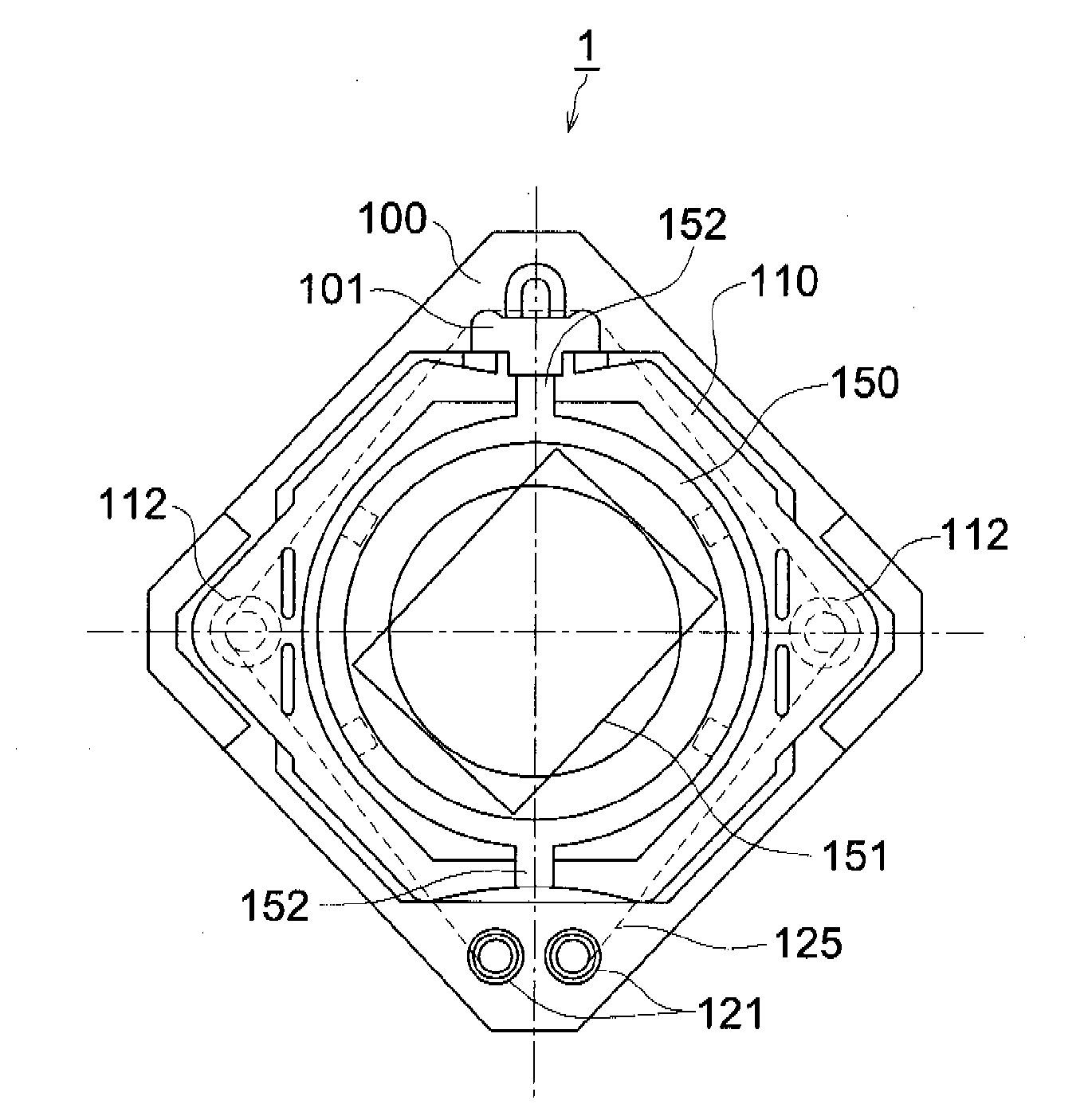
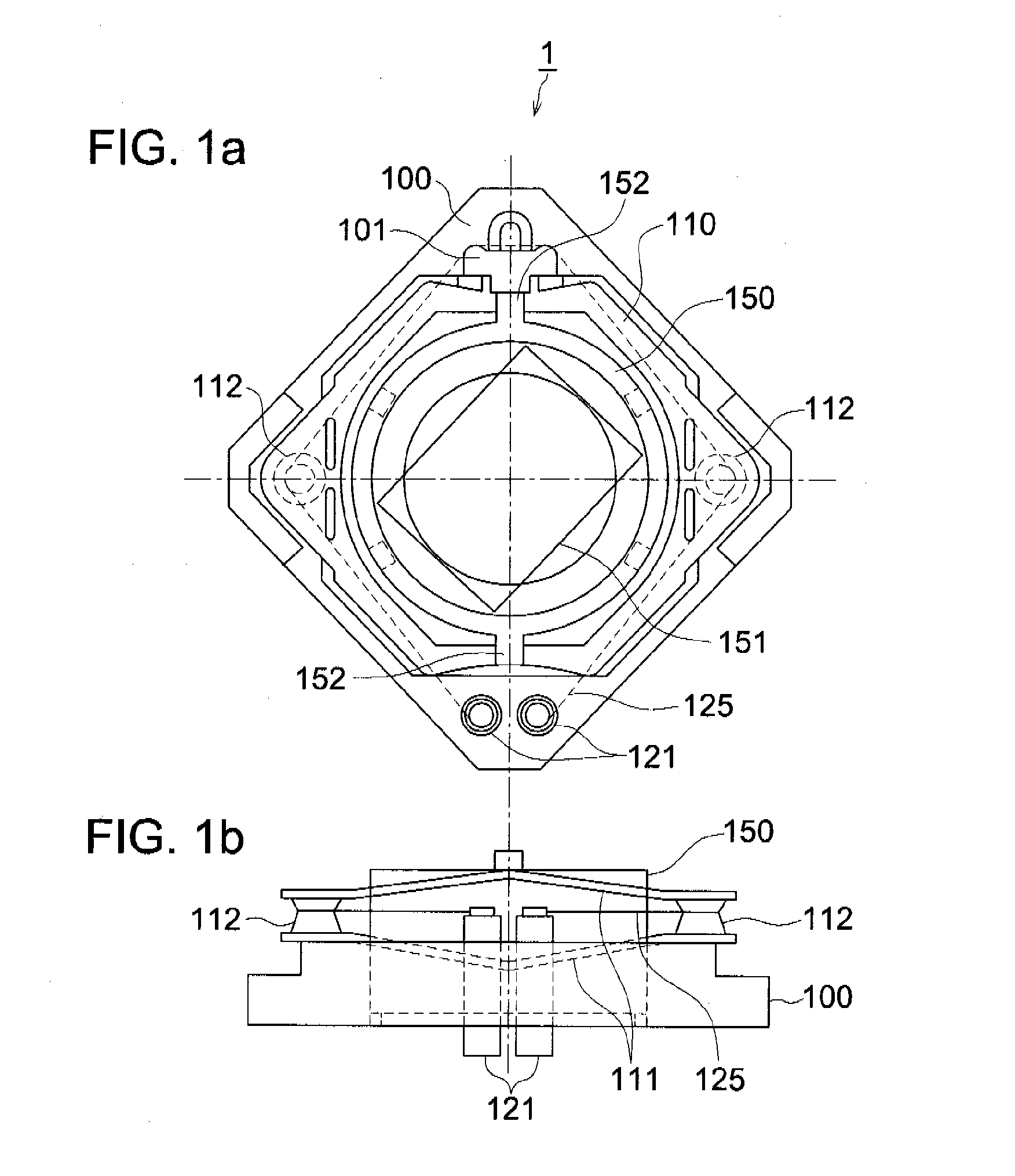
[0032]In the first place, the structure of the lens driving device will be explained with reference to FIGS. 1a and 1b. FIG. 1a is a plan view showing the external view of the lens driving device 1. FIG. 1b is a front view thereof.

[0033]As shown in FIG. 1a, the major portions of the lens driving device 1 include a base member 100, pantograph section 110, SMA fixing member 121, SMA 125, and lens barrel 150.

[0034]As shown in FIG. 1b, two rod-like metal SMA fixing members 121 are fixed in a form of penetrating the base member 100. The SMA fixing member 121 corresponds to the rod-like member of the present invention.

[0035]Both ends of the SMA 125 ...


PUM

PropertyMeasurementUnit
Pressureaaaaaaaaaa
Pressureaaaaaaaaaa
Diameteraaaaaaaaaa

Abstract

A driving device and driving device manufacturing method that ensure stable fixing of an SMA, without causing difficulties in downsizing the device, and without adversely affecting the performance of the SMA. A driving device equipped with a string-shaped shape memory alloy as a drive source includes a base member constituting a basis of the driving device, and a rod-like member which penetrates the base member and is made of the metal fixed onto this base member. The rod-like member is caulked on one end of this rod-like member so that the aforementioned shape memory alloy is pinch-held in-between, whereas power-feeding members to apply current to the shape memory alloy are arranged on the other end of the rod-like member.

Description

[0001]This application is based on Japanese Patent Application No. 2007-112826 filed on Apr. 23, 2007, in Japanese Patent Office, the entire content of which is hereby incorporated by reference.TECHNICAL FIELD[0002]The present invention relates to a driving device and method of manufacturing the same, particularly to a driving device provided with a shape memory alloy and method of manufacturing the same.[0003]BACKGROUND OF THE INVENTION[0004]In recent years, attempts have been made to use as actuators various forms of driving devices provided with a shape memory alloy (hereinafter referred to as “SMA”). The SMA is typically represented by a titanium-nickel alloy. It has a property that even if the SMA is deformed at a temperature lower than the temperature called “transformation point”, it goes back to the original state by martensite transformation when it is heated above that temperature. Normally, the SMA is made in the form of a string, and is expanded and contracted along the ...

Claims


Application Information

Patent Timeline
IPC IPC(8): F03G7/06H01R4/01
CPCY10T29/49174F03G7/06
Inventor WAKAHARA, JUNYAWADA, SHIGERU
Owner KONICA MINOLTA OPTO
Why Eureka
Try Eureka