Vapor Compression System With Condensate Intercooling Between Compression Stages

a technology of vapor compression system and compression stage, which is applied in the direction of defrosting, lighting and heating apparatus, and domestic cooling apparatus, to achieve the effects of improving the capacity of the refrigerant vapor compression system, enhancing the heat transfer surface, and improving the heat transfer

Inactive Publication Date: 2008-10-23
CARRIER CORP
View PDF16 Cites 46 Cited by
  • Summary
  • Abstract
  • Description
  • Claims
  • Application Information

AI Technical Summary

Problems solved by technology

However, because carbon dioxide has a low critical point, a vast majority of refrigerant vapor compression systems charged with carbon dioxide as the refrigerant are designed for operation in the transcritical cycle.

Method used


Image

  • Vapor Compression System With Condensate Intercooling Between Compression Stages
  • Vapor Compression System With Condensate Intercooling Between Compression Stages
  • Vapor Compression System With Condensate Intercooling Between Compression Stages

Examples


Embodiment Construction

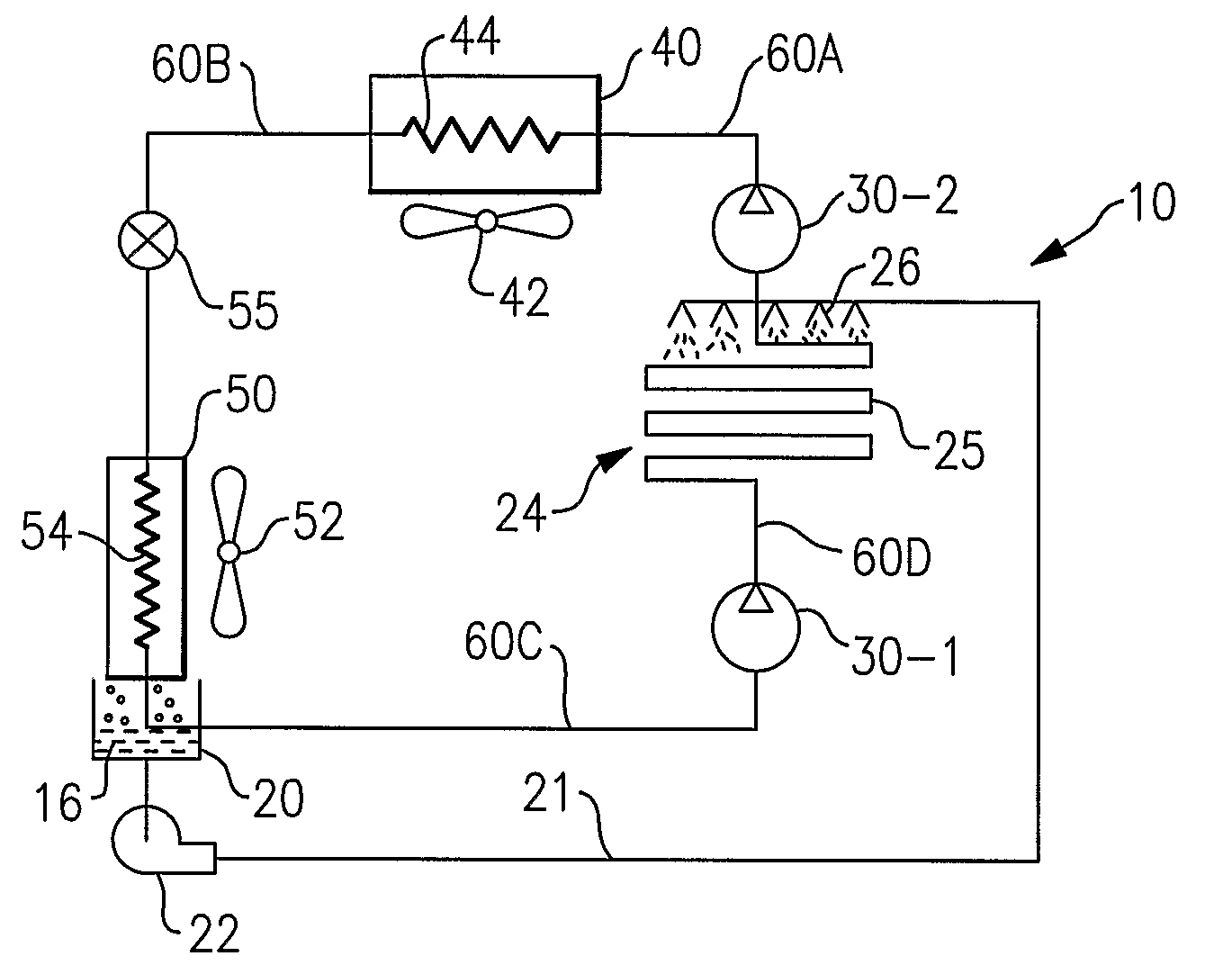
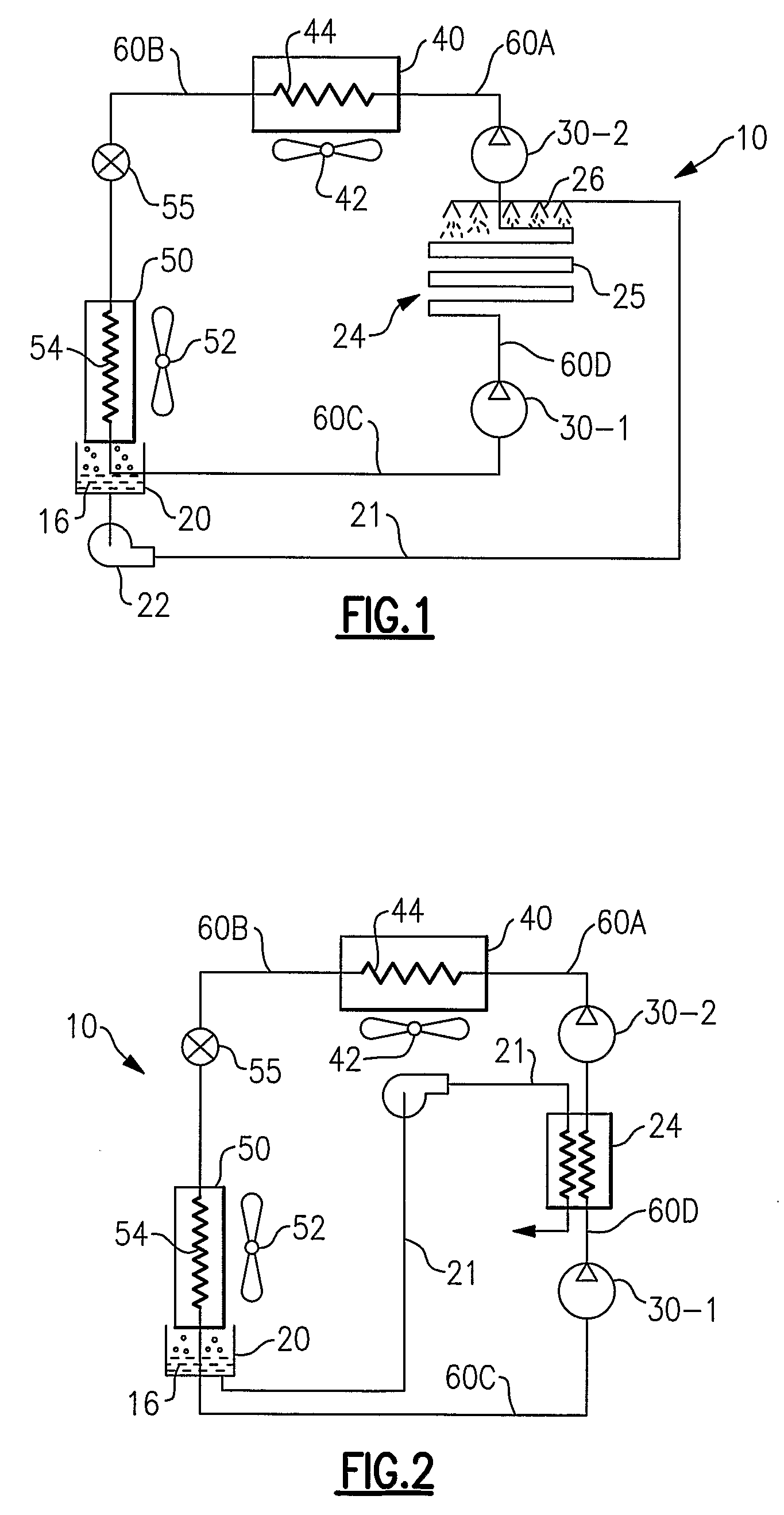
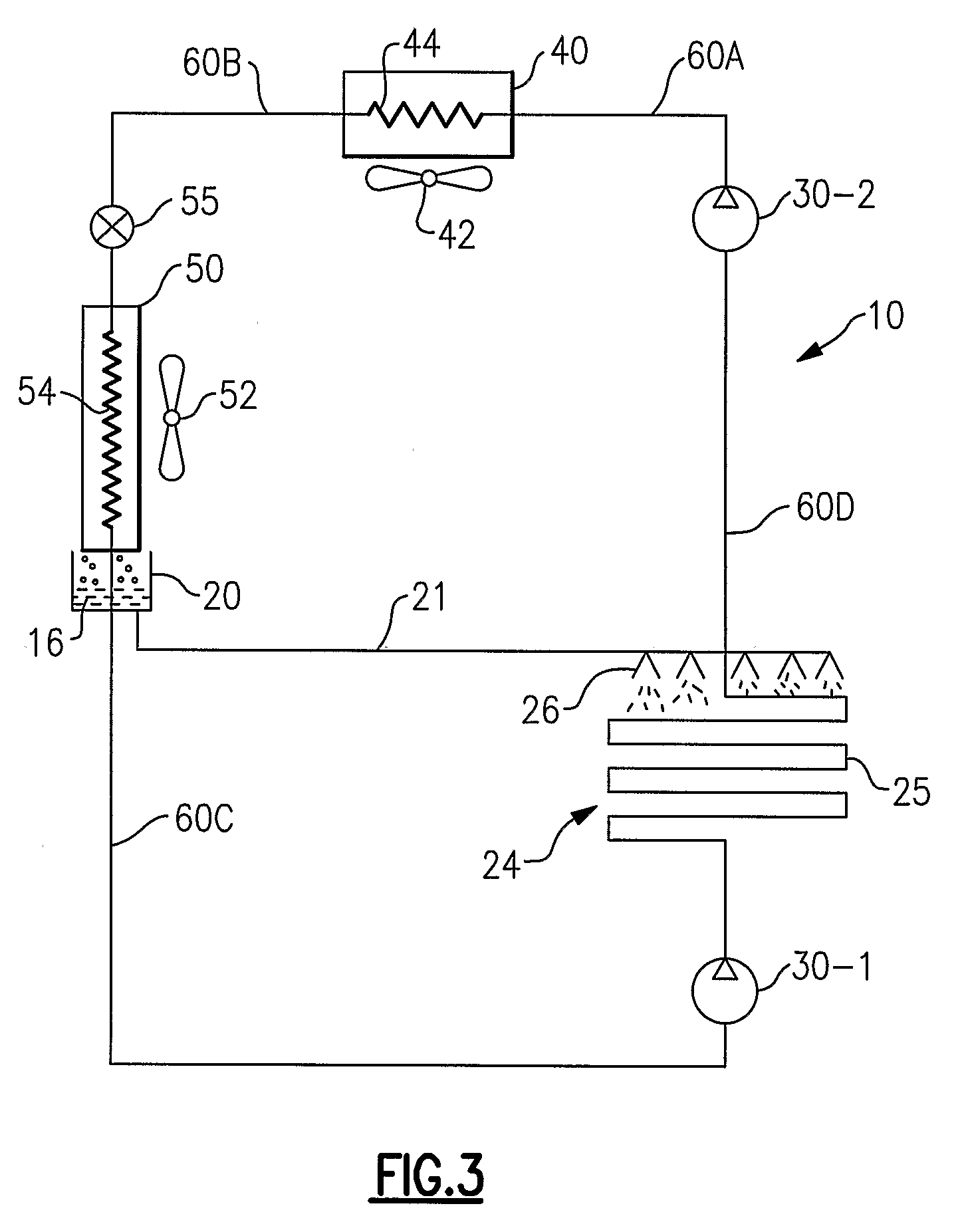
[0019]Referring now to FIGS. 1-4, as in conventional systems, the refrigerant vapor compression system 10 includes a compression device 30, a refrigerant heat rejecting heat exchanger 40, also referred to herein as a gas cooler or a condenser (depending on an application), a refrigerant heat absorbing heat exchanger 50, also referred to herein as an evaporator, an expansion device 55, illustrated as an expansion valve, operatively associated with the evaporator 50, and various refrigerant lines 60A, 60B, 60C and 60D connecting the aforementioned components in a conventional refrigerant circuit. The compression device 30 functions to compress and circulate refrigerant throughout the refrigerant circuit as will be discussed in further detail hereinafter. The compression device 30 may be a scroll compressor, a screw compressor, a reciprocating compressor, a rotary compressor, a centrifugal compressor or any other type of compressor or a plurality of any such compressors. The compressio...


PUM


Abstract

A refrigerant vapor compression system includes a first compression device and a second compression device disposed in a refrigerant circuit in series relationship with respect to refrigerant flow and an intercooler adapted to cool the refrigerant passing from the first compression device to the second compression. An evaporator is provided in the refrigerant circuit wherein the refrigerant accepts heat from a moisture bearing gas such as air. Condensate formed of moisture condensing out of the gas is collected and supplied to the intercooler for cooling the refrigerant flowing from the first compression device to the second compression device.

Description

FIELD OF THE INVENTION[0001]This invention relates generally to vapor compression systems having multiple compression stages and, more particularly, to the cooling of refrigerant vapor passing between an upstream compression stage and a downstream compression stage in a refrigerant vapor compression system.BACKGROUND OF THE INVENTION[0002]Refrigerant vapor compression systems are well known in the art and commonly used for conditioning secondary fluid such as air to be supplied to a climate controlled comfort zone within a residence, office building, hospital, school, restaurant or other facility. Refrigerant vapor compression systems are also commonly used in transport and stationary refrigeration applications for refrigerating air supplied to a temperature controlled space of a truck, trailer, container, display case or the like for preserving perishable items. Traditionally, most of these refrigerant vapor compression systems operate at subcritical refrigerant pressures and typic...

Claims


Application Information

Patent Timeline
Patent Type & Authority Applications(United States)
IPC IPC(8): F25B1/10F25B39/04F25B1/00
CPCF25B1/10F25B31/006F25B2400/072F25D21/14
Inventor LIFSON, ALEXANDERTARAS, MICHAEL F.
Owner CARRIER CORP
Why Eureka
Try Eureka