Belt retractor

a belt retractor and belt technology, applied in the field of belt retractors, can solve the problems of low price and small use of clip springs, and achieve the effects of simple production of clip springs, simple transportation of clip springs, and easy simulation of clip springs

Inactive Publication Date: 2008-10-23
TRW AUTOMOTIVE GMBH
View PDF6 Cites 5 Cited by
  • Summary
  • Abstract
  • Description
  • Claims
  • Application Information

AI Technical Summary

Benefits of technology

[0006]According to the invention there is used a clip spring which determines the basic position of the coupling disk with respect to the belt reel. The clip spring is distinguished by a plurality of advantages. The production of clip springs is simple, since among other things the spring force of the clip springs is solely adjusted by their tensioning, whilst in the case of spiral springs the spring force depends on the number of the spirals, the diameter thereof, etc. The material usage with clip springs is small, which is why clip springs are low-priced. Besides, the transport of clip springs is simple, since they cannot interlock. Therefore, no blister packages are required. When clip springs are used in belt retractors, the moment when the locking pawl is caused to engage is determined by the torque caused by the clip spring and the contact friction of the coupling disk on the reel axle. In the belt retractor in, accordance with the invention this frictional force is adjustable more variably than in the prior art. Depending on the forceless geometry of the clip spring (production state) a torque and a force between the coupling disk and the reel axle may be applied by the systematic tensioning in the state of installation. In the belt retractor in accordance with the invention the contact point of the clip spring to the coupling disk lies opposite the contact point of the locking pawl and is mounted rotatably. The radial component of the tensioning force may, for example, be used to change the amount and the direction of the frictional force caused by the weight of the locking pawl such that the frictional force depends less on the position of the locking pawl. A frictional force whose amount is more constant than in the prior art therefore results in a more defined breakaway in all positions of the locking pawl. Besides, in spiral springs used in the prior art disturbing noises occurred on account of the spirals striking against one another, which is known as “spring whizzing” and which is absent in clip springs. Furthermore, clip springs may be simulated more easily. It is, moreover, advantageous that clip springs have a higher resistance to the action of a tensioner, since they do not become entangled in a higher acceleration.
[0007]Preferably, the clip spring is configured symmetrically and therefore does not have to be oriented relative to the reel axle prior to the installation, i.e., it does not have to be rotated. Therefore, the installation is simple.
[0008]Preferably, the belt reel includes a reel axle, and the coupling disk is mounted on the reel axle, the clip spring being attached to the belt reel and to the coupling disk such that it does not engage the reel axle. Since the clip spring does not engage the reel axle, the latter is not stressed, and disturbing noises are avoided.

Problems solved by technology

The material usage with clip springs is small, which is why clip springs are low-priced.
Besides, in spiral springs used in the prior art disturbing noises occurred on account of the spirals striking against one another, which is known as “spring whizzing” and which is absent in clip springs.

Method used


Image

  • Belt retractor
  • Belt retractor
  • Belt retractor

Examples


Embodiment Construction

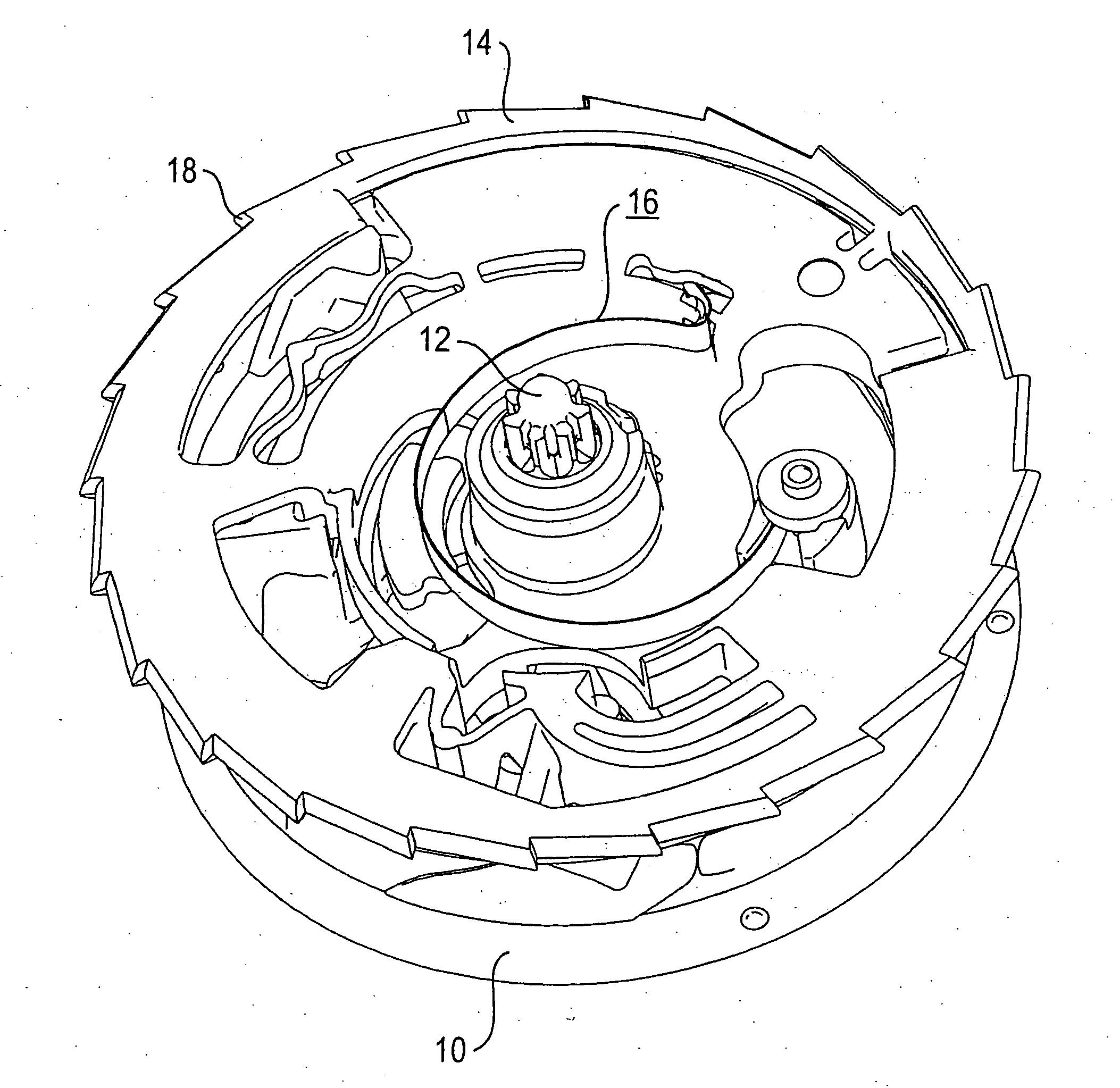
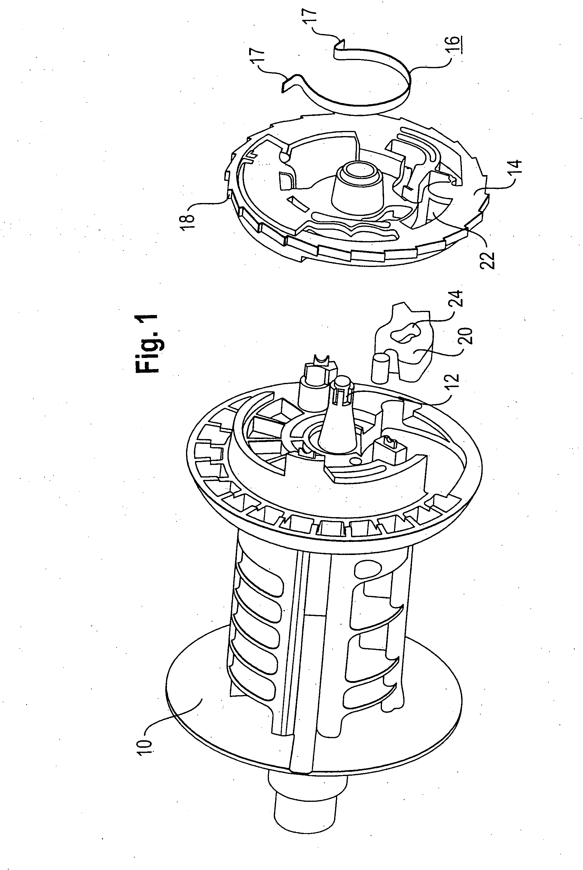
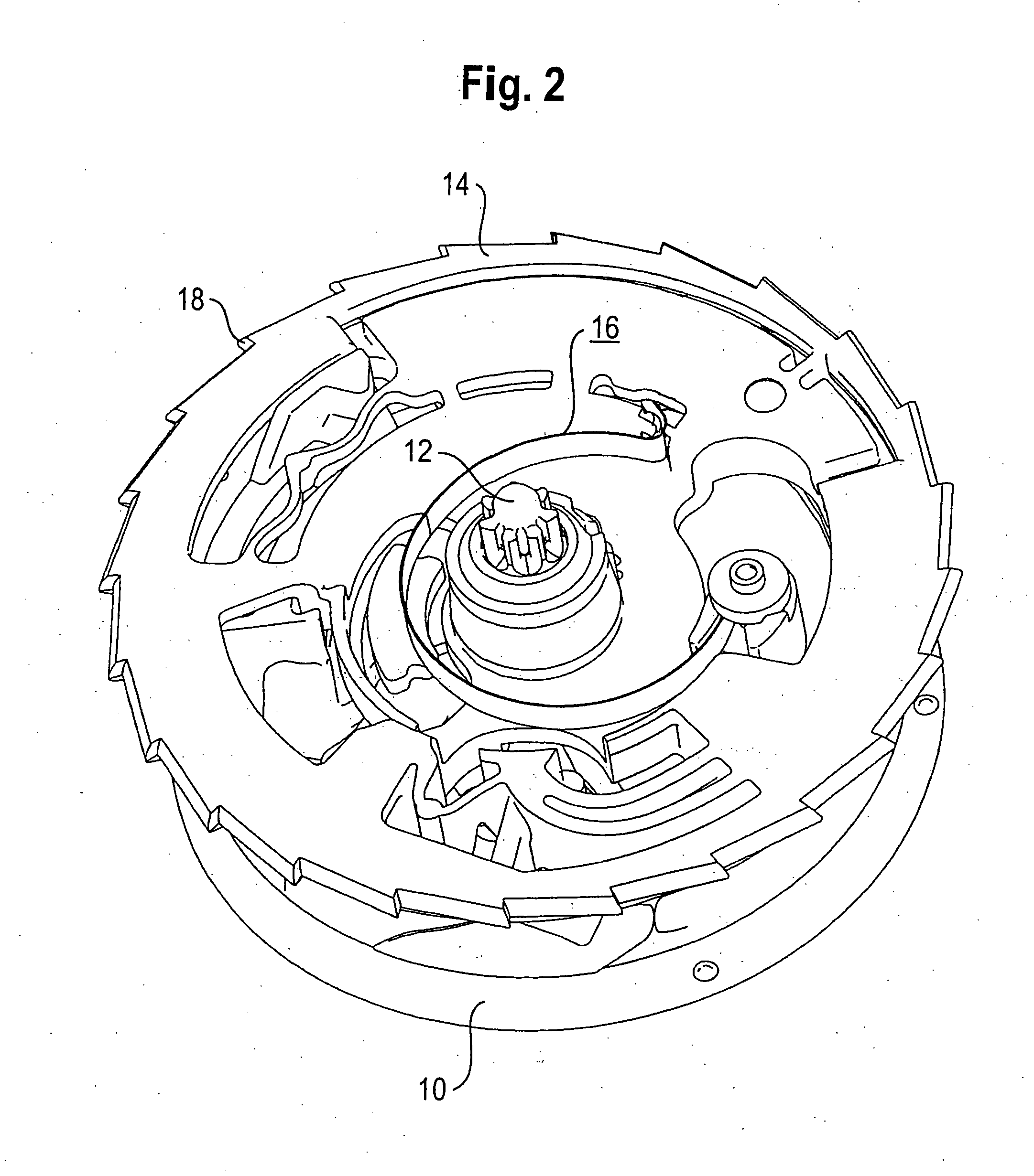
[0013]There is provided a coupling disk 14 which is coaxially connected to the belt reel 10. The basic position of the coupling disk 14 with respect to the belt reel 10 is determined by a clip spring 16, the first end of the clip spring 16 being attached to the coupling disk 14 and its second end being attached to the belt reel 10 (FIGS. 2 and 3), in particular, in such a manner that the clip spring 16 does not engage the reel axle 12 and such that it is tensioned. The clip spring 16 is directly attached to the coupling disc 14. For the attachment to the coupling disk 14 and to the belt reel 10, the ends of the clip spring 16 are bent in the shape of hooks (the hooks 17). The clip spring 16 is eccentrically attached to the belt reel 10 and to the coupling disk 14 (with respect to the reel axle 12) and rotatably supported on the coupling disk 14.

[0014]On its outer periphery the coupling disk 14 is provided with a toothing 18 which may cooperate with a vehicle-sensitive sensor element...


PUM


Abstract

A belt retractor for a vehicle safety belt with a frame has a belt reel (10) rotatably mounted in the frame, a coupling disk (14) rotatably mounted relative to the belt reel (10), and a clip spring (16) which is attached to the belt reel (10) and to the coupling disk (14).

Description

TECHNICAL FIELD [0001]The invention relates to a belt retractor for a vehicle safety belt.BACKGROUND OF THE INVENTION [0002]The belt retractor serves to make the vehicle safety belt available to a vehicle occupant. In the normal operating state the vehicle safety belt may be unwound from a belt reel or wound up again on the same. There is provided a locking mechanism which is capable of blocking the belt reel in a manner sensitive to the belt webbing or in a vehicle-sensitive manner, hence dependent on parameters such as the belt webbing or vehicle acceleration. For the vehicle or belt webbing sensitive blocking of the belt reel modern belt retractors have a coupling disk which rotates along with the belt reel in the normal operating state. For the vehicle-sensitive activation of the locking mechanism the coupling disk is provided with a toothing, a locking element of a vehicle-sensitive sensor being able to engage in the toothing. An inertial element is connected to the coupling di...

Claims


Application Information

Patent Timeline
Patent Type & Authority Applications(United States)
IPC IPC(8): B65H75/18
CPCB60R22/40B60R22/405
Inventor BLUM, HERBERTKNOESS, STEFAN
Owner TRW AUTOMOTIVE GMBH
Why Eureka
Try Eureka