Optical Detector

a detector and optical technology, applied in the field of optical detection, can solve the problems of short path length for light, insensitive ce with some analytes, and rapid separation of many hundreds of different compounds

Inactive Publication Date: 2008-10-23
UNIV COLLEGE CORK NAT UNIV OF IRELAND CORK
View PDF8 Cites 13 Cited by
  • Summary
  • Abstract
  • Description
  • Claims
  • Application Information

AI Technical Summary

Benefits of technology

[0014]Thus, the incident radiation is directed particularly accurately for optimum sensing of the response radiation. This is particularly advantageous for applications involving low radiation intensities and physically-constrained situations such as inside the body for medical analysis.
[0015]In one embodiment, the sensor substrate allows said incident radiation to pass through it. This allows a particularly compact configuration.
[0017]In one embodiment, the sensor comprises a plurality of sensor devices, and said devices surround the guide. This allows very effective sensing or response radiation spread over a relatively large cross-sectional area compared with the cross-sectional area of the incident radiation.
[0019]In one embodiment, the sensor comprises an integrated circuit incorporating the sensor devices. This is a particularly compact and effective arrangement. In one embodiment, the guide passes through the integrated circuit. This allows particularly good accuracy.
[0026]In one embodiment, said filter is transparent to the response radiation and opaque to the incident radiation. This allows excellent integrity in the sensing of radiation.

Problems solved by technology

These analyses, all driven by an electric field, are performed in narrow tubes and can result in the rapid separation of many hundreds of different compounds.
However a problem with the use of CE capillaries for a detection cell comes about because of the very narrow nature of the capillary.
Another problem is that the capillary being thin results in a very short path length for the light.
This can lead to CE being somewhat insensitive with some analytes.
They may lack a chromophore and be unsuitable for use with phosphate and borate buffers.

Method used


Image

  • Optical Detector
  • Optical Detector
  • Optical Detector

Examples


Embodiment Construction

Brief Description of the Drawings

[0041]The invention will be more clearly understood from the following description of some embodiments thereof, given by way of example only with reference to the accompanying drawings in which:

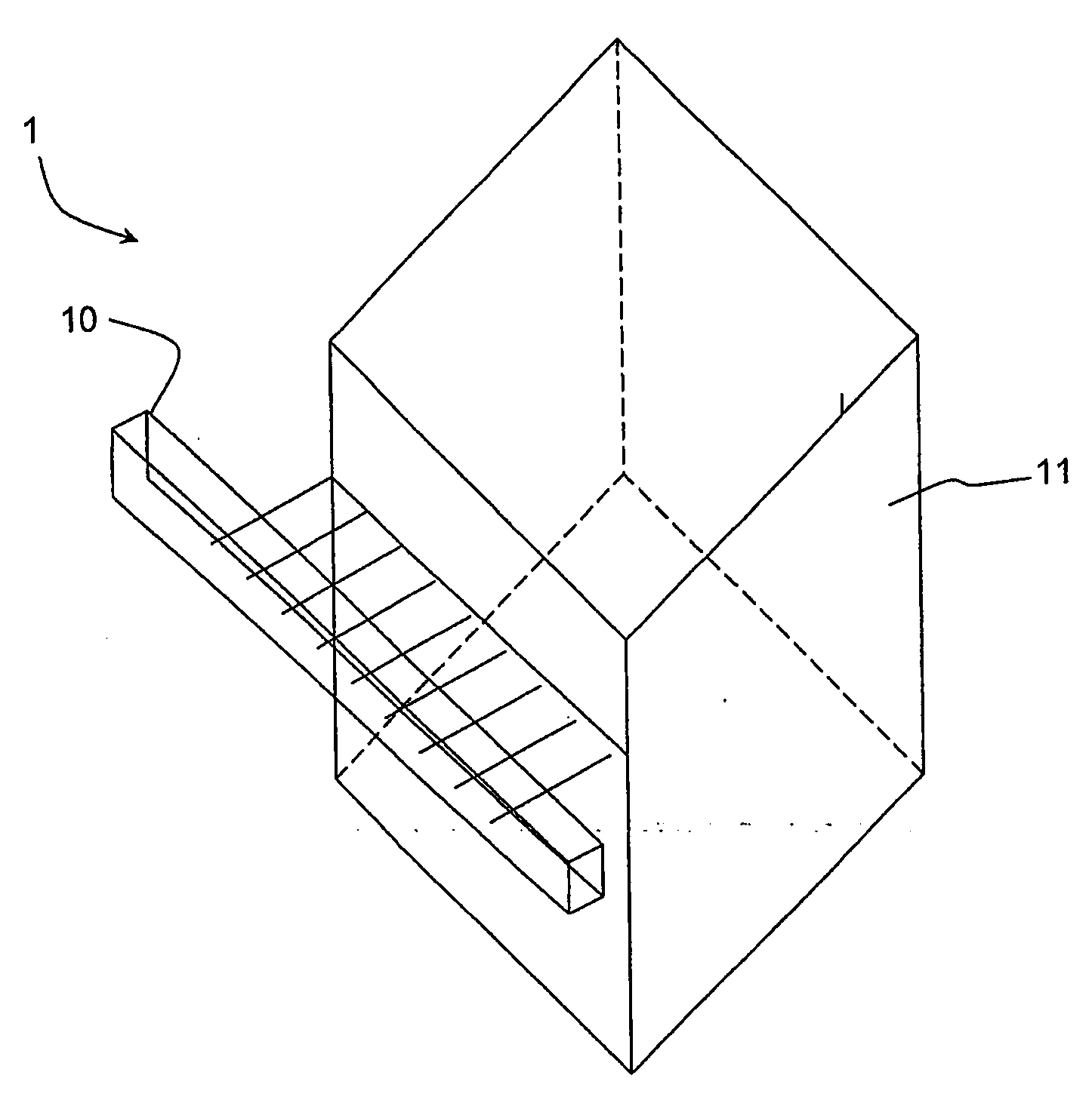
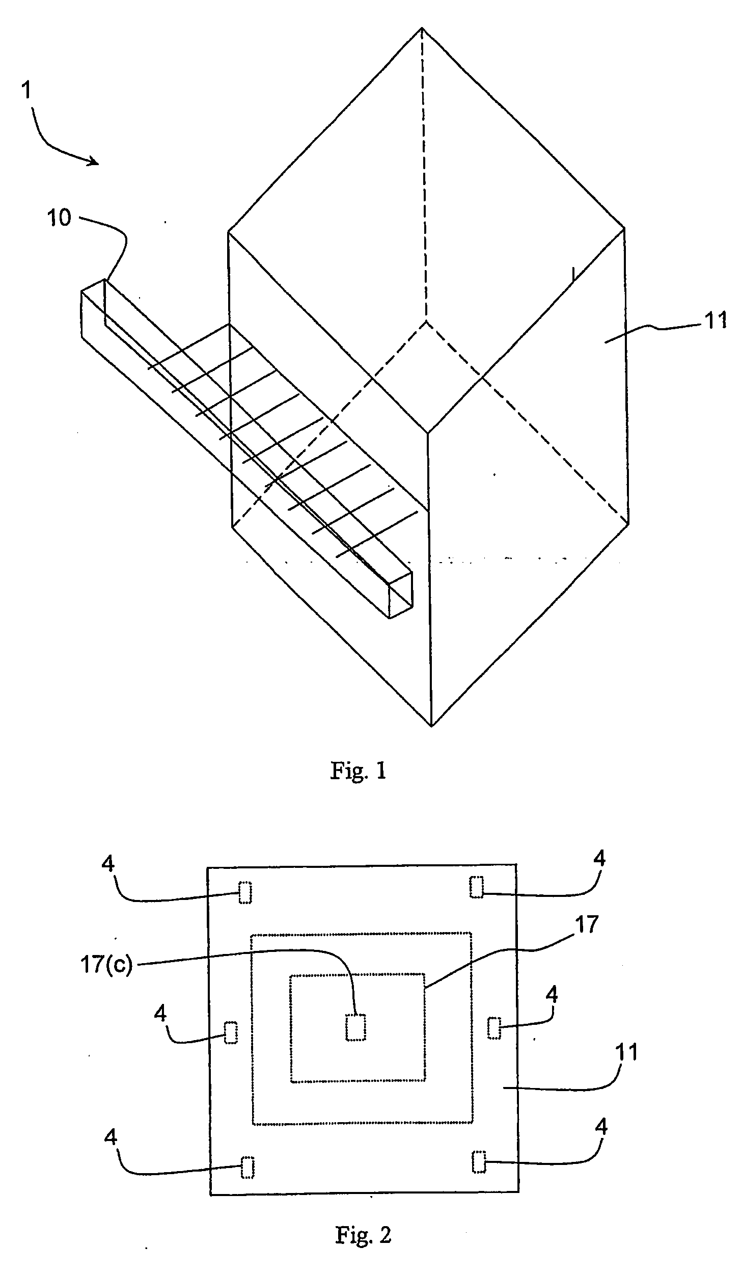
[0042]FIG. 1 is a diagrammatic perspective view from above of an optical detector of the invention, and

[0043]FIG. 2 is an underneath plan view;

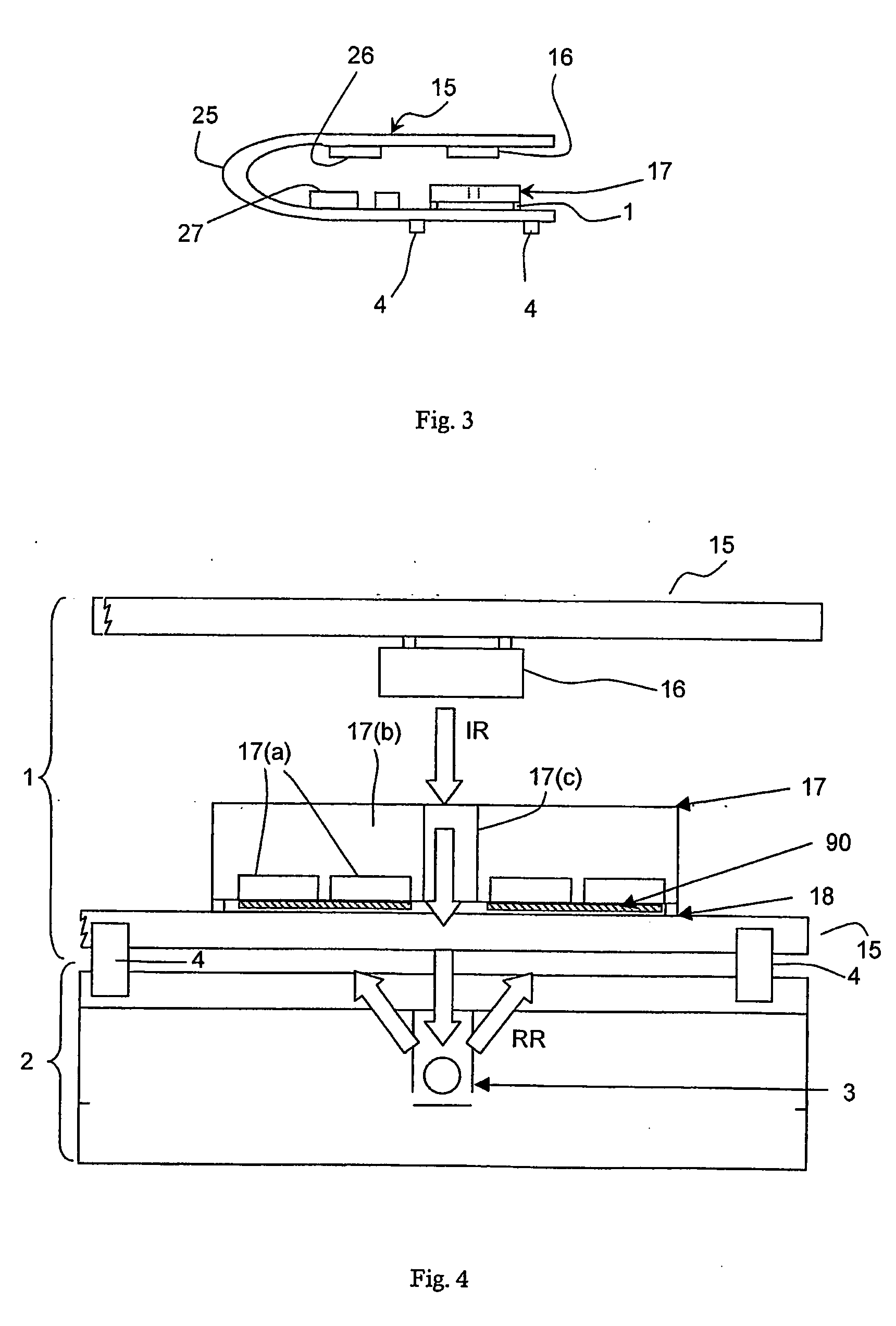
[0044]FIG. 3 is a general side view, before encapsulation, showing the arrangement of a substrate of the detector;

[0045]FIG. 4 is a cross-sectional diagram illustrating the detector in more detail and showing how it is coupled with a microfluidic system to detect a sample in a channel of the microfluidic system;

[0046]FIG. 5 is a cross-sectional diagram illustrating an alternative embodiment in a similar manner; and

[0047]FIG. 6 is a cross-sectional diagram showing a further optical detector of the invention.

DESCRIPTION OF THE EMBODIMENTS

[0048]Referring to FIGS. 1 to 4 there is shown an optical detector 1 which acts as a ...


PUM

PropertyMeasurementUnit
wavelengthaaaaaaaaaa
detection wavelengthsaaaaaaaaaa
IR wavelengthaaaaaaaaaa

Abstract

An optical detector (1) acts as a modular detection unit. It may for example be mounted on a separate micro-fluidic device (2) for detection of species within a channel (3) of the device (2). The detector (1) has mounting lugs (4) for mounting on the micro-fluidic device (2) for exact registry with the channel (3). A substrate (15) is folded over at a flexible part (25) through 180° and, at the top, supports a vertical emitting laser device (16). The lower branch of the substrate (15) supports an integrated circuit photo-diode array sensor (17) having chip bumps (18). The substrate (15) also supports emitter drive circuitry (26) and detector circuitry (27). The sensor (17) is a silicon integrated circuit, having an array of integrated photo-diodes (17(a)) in a silicon wafer (17(b)). There is a vertical through-hole (17(c)) in the wafer, to act as a guide for incident radiation emitted by the emitter (16) (arrows IR). Because of the single folded-over substrate arrangement the emitter 16 can be particularly easily and accurately aligned with the guide aperture 17(c).

Description

INTRODUCTION[0001]1. Field of the Invention[0002]The invention relates to optical detection for analysis of samples.[0003]2. Prior Art Discussion[0004]Capillary electrophoresis, or CE, describes a family of techniques used to separate a variety of compounds. These analyses, all driven by an electric field, are performed in narrow tubes and can result in the rapid separation of many hundreds of different compounds. The versatility and number of ways that CE can be used means that almost all molecules, and even whole organisms can be separated.[0005]UV-visible absorption is the most common detection method because it is simple to use and most analytes can be observed with it. It is also a tested method for other chromatographic analyses and can be used quantitatively. When using fused silica capillaries it is possible to use detection wavelengths down to about 200 nm. A window is burnt in the polyamide protecting the capillary and UV light can be shone through and absorbed by passing ...

Claims


Application Information

Patent Timeline
Patent Type & Authority Applications(United States)
IPC IPC(8): G01N23/00
CPCG01N21/6454
Inventor MATHEWSON, ALANALDERMAN, JOHNJACKSON, JOHN CARLTON
Owner UNIV COLLEGE CORK NAT UNIV OF IRELAND CORK
Why Eureka
Try Eureka