
Semiconductor device manufacturing method and display device

a semiconductor device and manufacturing method technology, applied in the direction of transistors, crystal growth processes, chemistry apparatuses and processes, etc., can solve the problems of difficult to eliminate the variations between the irradiating optical systems completely, the laser output variation between the irradiating optical systems is variable, etc., to suppress the adverse effects of the variation in the intensity of the energy beam, suppress the non-uniformity of the display, and enhance the productivity of the semiconductor device

Inactive Publication Date: 2008-10-23
SONY CORP
View PDF5 Cites 5 Cited by
  • Summary
  • Abstract
  • Description
  • Claims
  • Application Information

AI Technical Summary

Benefits of technology

[0009]The present invention has been made in view of such problems. It is desirable to provide a semiconductor device manufacturing method that can suppress effects of variations in intensity between the laser beams of respective irradiating optical systems even when the plurality of irradiating optical systems are used to enhance productivity, and a display device that can suppress display nonuniformity and enhance display quality by being formed with a semiconductor device manufactured by the manufacturing method.
[0013]According to an embodiment of the present invention, even when an annealing process is performed on a semiconductor film by using a plurality of irradiating optical systems to thereby enhance the productivity of a semiconductor device, it is possible to suppress adverse effects of variations in energy beam intensity between the irradiating optical systems. Thus, when a display device is constructed with TFTs formed on the semiconductor film obtained through the annealing process, for example, it is possible to suppress display nonuniformity caused by difference in luminance and thereby achieve high display quality. This is effective especially when applied to an organic electroluminescent display device whose light emitting performance tends to be affected by difference in characteristics of TFTs.

Problems solved by technology

However, when a plurality of laser beams are used, as shown in FIG. 15A, for example, errors in adjustment of irradiating optical systems or the like may result in variations in laser output between the irradiating optical systems.
It is often difficult to eliminate these variations between the irradiating optical systems completely.

Method used


Image

  • Semiconductor device manufacturing method and display device
  • Semiconductor device manufacturing method and display device
  • Semiconductor device manufacturing method and display device

Examples


Embodiment Construction

[0029]A semiconductor device manufacturing method and a display device according to embodiments of the present invention will hereinafter be described with reference to the drawings.

[General Constitution of Display Device]

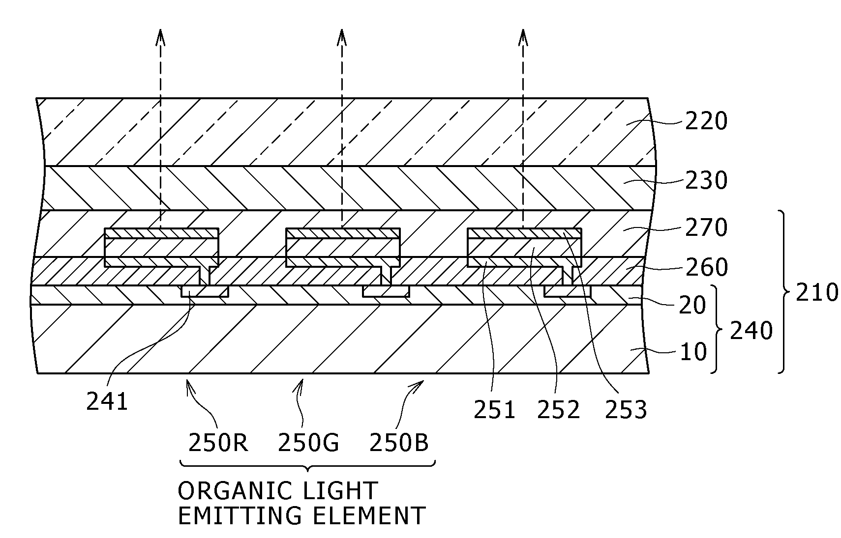
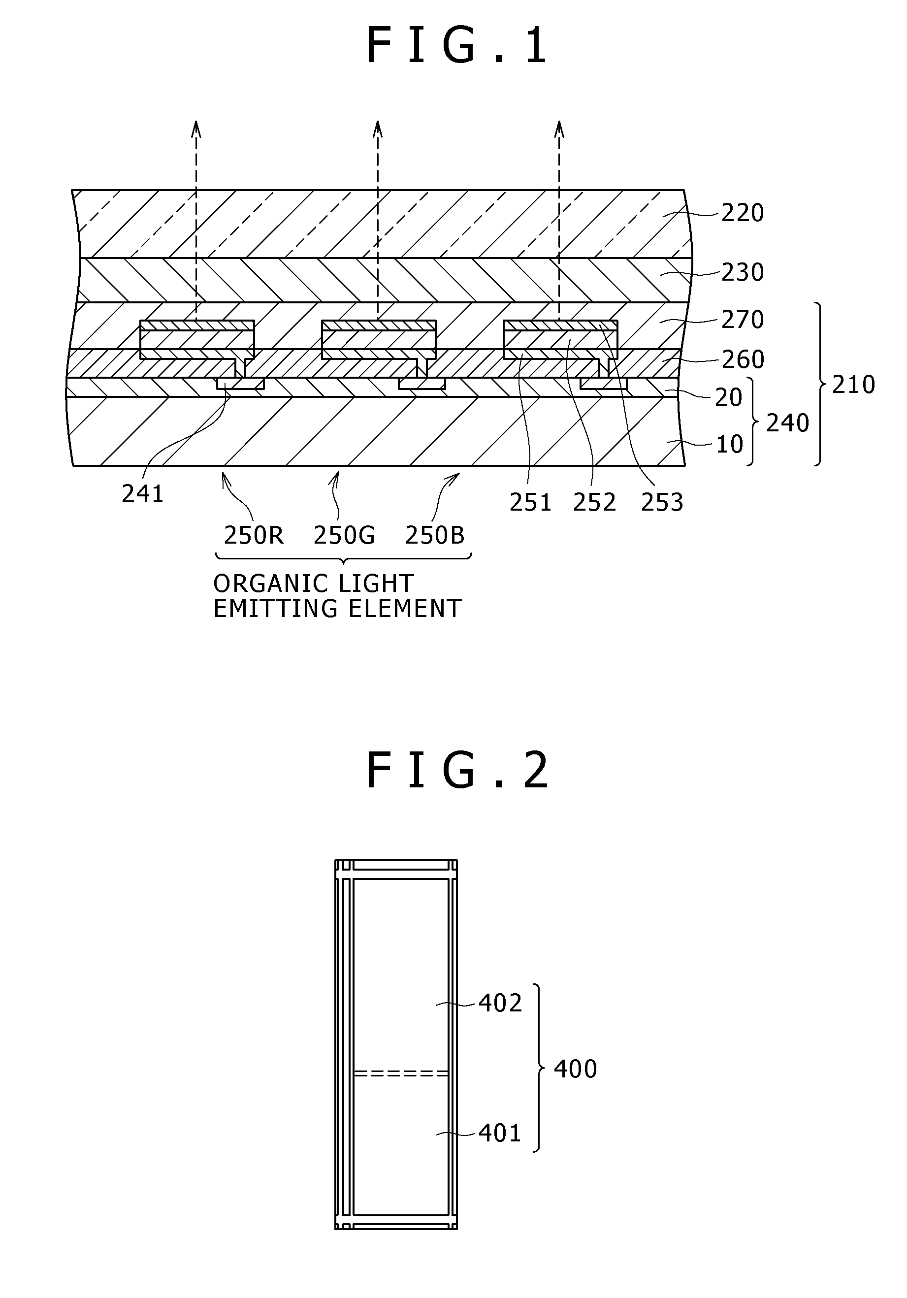
[0030]A general constitution of a display device will first be described by taking an organic EL display device as an example.

[0031]FIG. 1 is a diagram of assistance in explaining an example of a general constitution of an organic EL display device.

[0032]The display device shown in FIG. 1 is used as an active or passive type very thin organic EL display device driven by a TFT, for example. The display device is formed by arranging a driving panel 210 and a sealing panel 220 such that the driving panel 210 and the sealing panel 220 are opposed to each other, and laminating the driving panel 210 and the sealing panel 220 to each other with an adhesive layer 230 formed by a thermosetting resin or an ultraviolet curing resin interposed between the driving panel 210 and...


PUM


Abstract

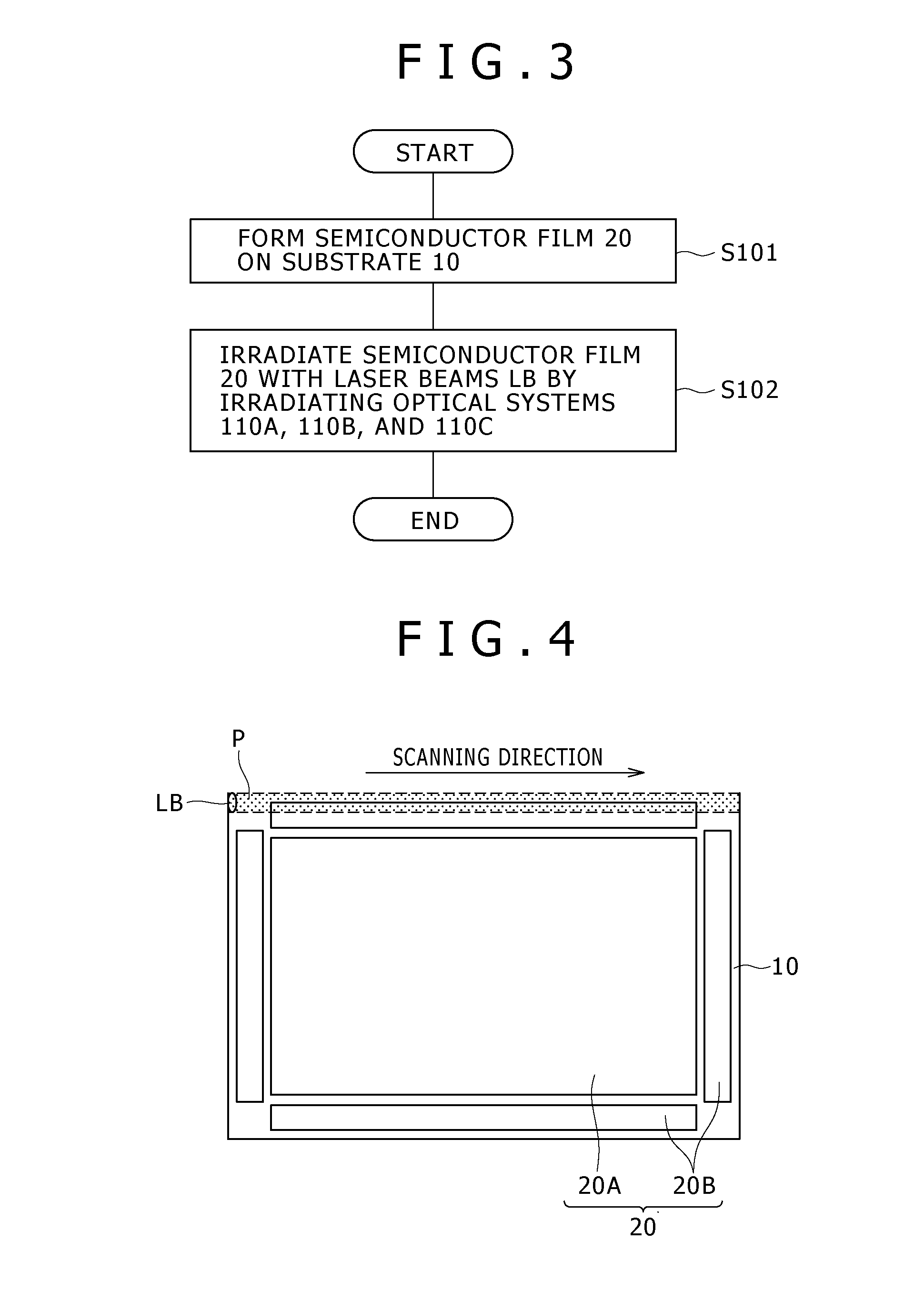
Disclosed herein is a semiconductor device manufacturing method for performing an annealing process of irradiating a semiconductor film on which element forming areas including thin film transistor forming areas are arranged in a two-dimensional pattern with energy beams using a plurality of irradiating optical systems, wherein in the annealing process, an area irradiated with the energy beams is divided into a single beam irradiated area irradiated by each of the plurality of irradiating optical systems with an energy beam singly and a boundary area situated between single beam irradiated areas adjacent to each other and irradiated by both of two irradiating optical systems performing beam irradiation of the single beam irradiated areas with energy beams.

Description

CROSS REFERENCES TO RELATED APPLICATIONS[0001]The present invention contains subject matter related to Japanese Patent Application JP 2007-111793 filed in the Japan Patent Office on Apr. 20, 2007, the entire contents of which being incorporated herein by reference.BACKGROUND OF THE INVENTION[0002]1. Field of the Invention[0003]The present invention relates to a semiconductor device manufacturing method suitable for manufacturing a thin film transistor (hereinafter abbreviated to a “TFT”) substrate used in for example a liquid crystal display device or an organic electroluminescent device, and a display device including a semiconductor film manufactured by the method.[0004]2. Description of the Related Art[0005]When a high-value-added active matrix type liquid crystal display device referred to as a system liquid crystal, an organic electroluminescent display device (hereinafter referred to as an “organic EL display device”) using an organic electroluminescent element (hereinafter re...

Claims


Application Information

Patent Timeline
IPC IPC(8): H01L33/00H01L21/00H01L21/20H01L21/336H01L29/786
CPCH01L27/3211H01L27/1285Y10S117/904H01L51/5281H10K59/35H10K59/8791H10K50/86
Inventor ARAI, TOSHIAKI
Owner SONY CORP
Learn More