Magnetic resonance imaging visualization method and system

a magnetic resonance imaging and visualization method technology, applied in the field of image processing, can solve the problems of wasting time, wasting resources, and wasting resources, and achieving the effect of reducing the cost of image processing

Active Publication Date: 2008-10-23
GENERAL ELECTRIC CO
View PDF5 Cites 3 Cited by
  • Summary
  • Abstract
  • Description
  • Claims
  • Application Information

AI Technical Summary

Problems solved by technology

Similarly, 3-D images may also be formed, however, such constructions directly from k-space are unfortunately computationally laborious and, therefore, quite lengthy.
Moreover, applying ...

Method used


Image

  • Magnetic resonance imaging visualization method and system
  • Magnetic resonance imaging visualization method and system
  • Magnetic resonance imaging visualization method and system

Examples


Embodiment Construction

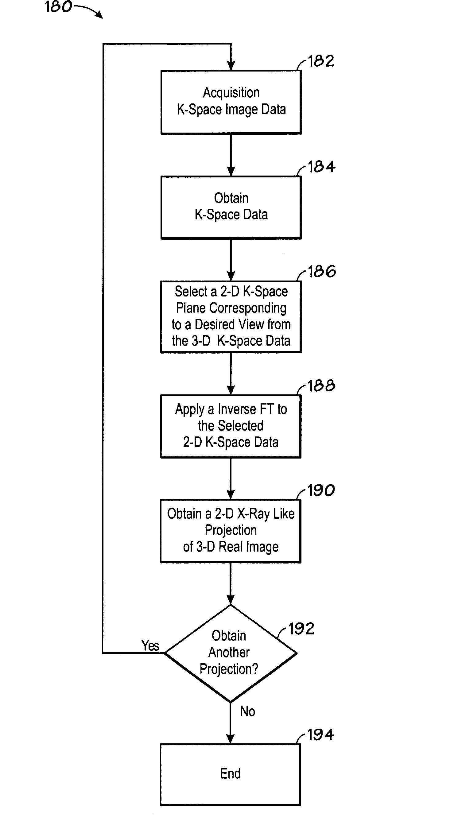
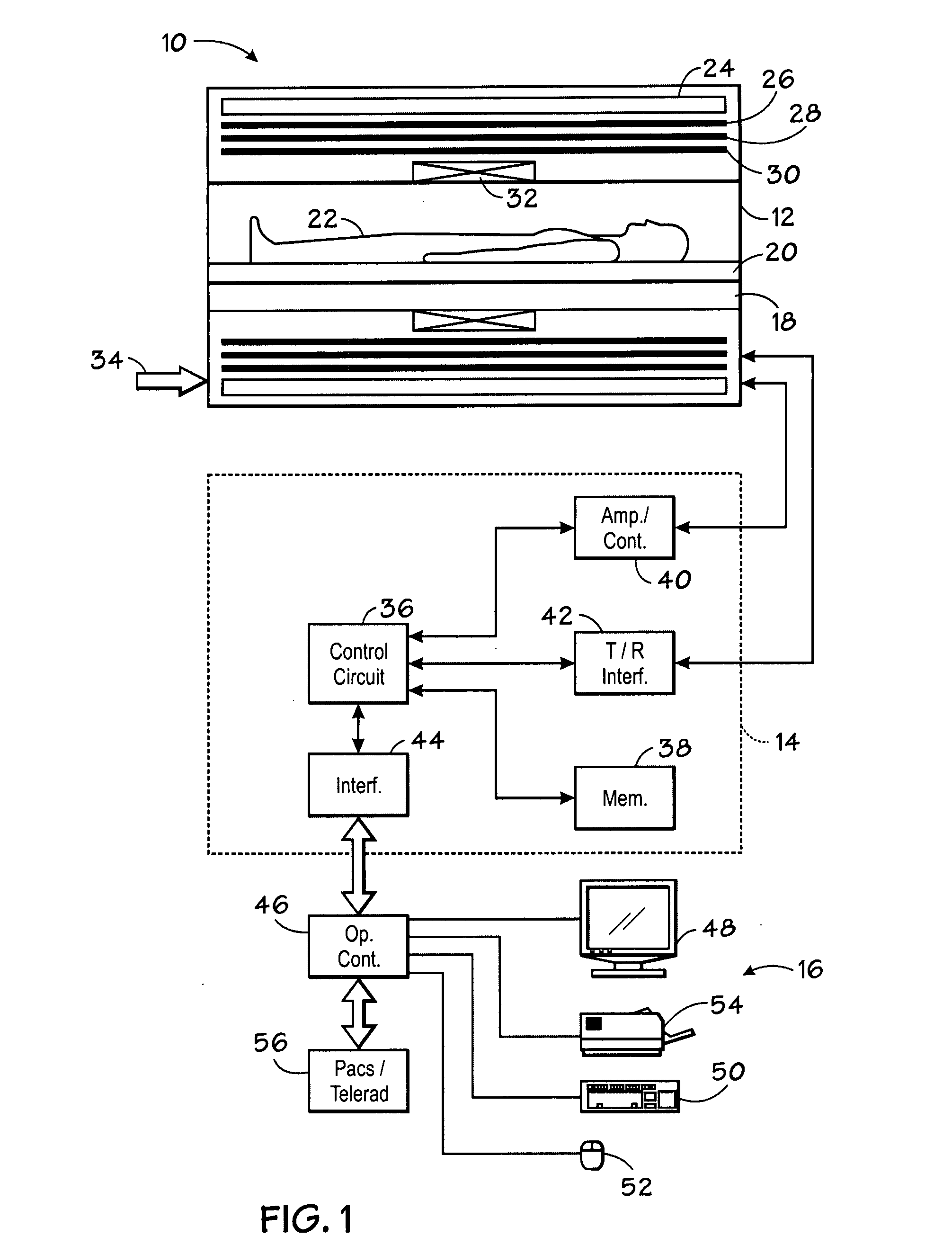
[0015]Turning now to the drawings, and referring first to FIG. 1, a magnetic resonance imaging (MRI) system 10 is illustrated diagrammatically as including a scanner 12, scanner control circuitry 14, and system control circuitry 16. As further discussed below, MRI system 10 may be adapted to initially acquire two and three-dimensional image data in k-space from which projection images of an imaged object may be formed using the Fourier projection-slice theorem.

[0016]While MRI system 10 may include any suitable MRI scanner or detector, in the illustrated embodiment the system includes a full body scanner comprising a patient bore 18 into which a table 20 may be positioned to place a patient 22 in a desired position for scanning. Scanner 12 may be of any suitable type of rating, including scanners varying from 0.5 Tesla ratings to 1.5 Tesla ratings and beyond.

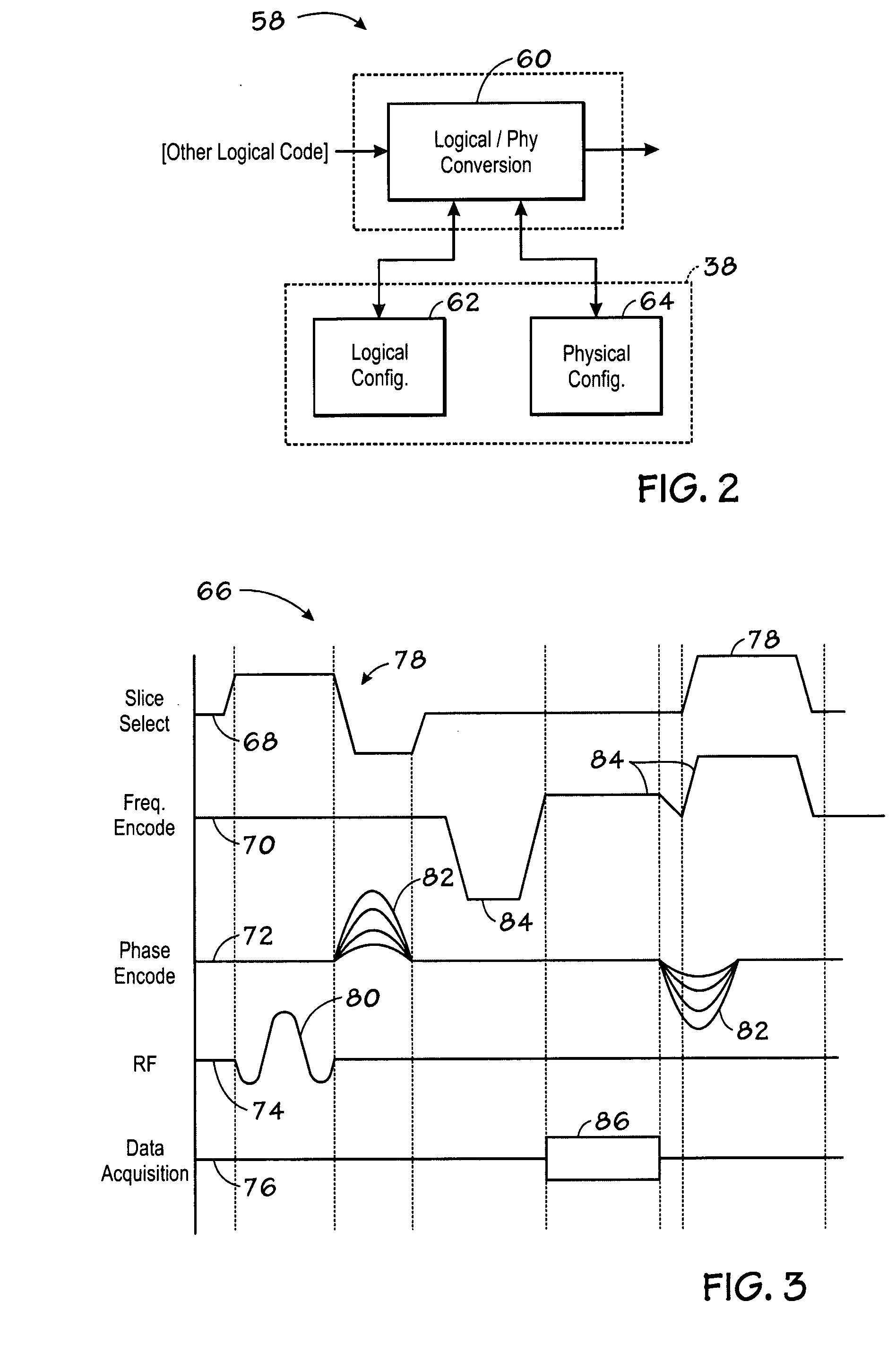
[0017]Scanner 12 includes a series of associated coils for producing controlled magnetic fields, for generating radiofrequency ...


PUM


Abstract

The present technique provides a system and method for processing an image. Particularly the method comprises acquiring image data in frequency space (k-space) of an imaged volume and obtaining a three-dimensional (3-D) k-space volume representative of the imaged volume based on the acquired k-space data. The method further comprises selecting a two-dimensional (2-D) plane from the 3-D k-space volume and applying an inverse Fourier transform to the selected 2-D plane to obtain a real 2-D X-ray-like (or enhanced rendering) projection of the imaged volume offering insights into the 3-D data.

Description

BACKGROUND[0001]The invention relates generally to image processing. Particularly, this invention relates to a volume rendering techniques used in magnetic resonance imaging (MRI).[0002]MRI systems have become ubiquitous in the field of medical diagnostics. In general, MRI imaging techniques are based on the interactions among a primary magnetic field, a radiofrequency (rf) field and time varying magnetic gradient fields that combine to influence nuclear spins within the subject of interest. Specific nuclear components, such as hydrogen nuclei in water molecules, have characteristic behaviors in response to external magnetic fields. The precession of spins of such nuclear components can be influenced by manipulation of the fields to obtain rf signals that can be detected, processed, and used to reconstruct a useful image.[0003]The magnetic fields used to produce images in MRI systems include a highly uniform, static magnetic field that is produced by a primary magnet. A series of gr...

Claims


Application Information

Patent Timeline
IPC IPC(8): G01V3/38G06K9/36
CPCG01R33/56G01R33/5608
Inventor MULLICK, RAKESH
Owner GENERAL ELECTRIC CO
Why Eureka
Try Eureka