An apparatus and method for detecting an interventional tool

a technology of interventional tools and apparatus, applied in the field of apparatus and methods for detecting tools, can solve the problems of excluding parts of the tool from the ultrasound image, misalignment of the tool, and limited 2d imaging field of view, and achieves the effect of rapid identification, less sensitive to noise, and rapid visualization of the tool to the operator

Active Publication Date: 2019-07-04
KONINKLJIJKE PHILIPS NV
View PDF0 Cites 8 Cited by
  • Summary
  • Abstract
  • Description
  • Claims
  • Application Information

AI Technical Summary

Benefits of technology

[0024]The invention allows to further improve the precision of the tool's location detection by comparing different differential shadow regions derived from two different pairs of the reconstructed ultrasound image. The correlation of these regions with each other, namely region parameters such as area, size and its location within a respective reconstructed ultrasound image, and with the steering angles of corresponding images wherefrom these regions were identified allows the imaging processing unit to determine the locations of the tool within the volumetric region with even better precision.
[0028]In 3D ultrasound imaging, a 3D ultrasound imaging apparatus is arranged to control the ultrasound array to emit ultrasound radiation (in other words steer beams) towards a subject and to detect radiation reflected by the subject to produce a 3D ultrasound volume data set which represents a 3D volume of the subject. In this way, the 3D imaging apparatus produces an image of the 3D volume. Based on the acquired 3D ultrasound image data the image processing unit is arranged to reconstruct a 3D ultrasound image comprising a plurality of image planes. The tip tool detection module may be further arranged to select from said plurality of planes at least two image planes corresponding to different steering angles, wherein each of the planes includes a tool shadow region. Therefore, by acquiring one 3D ultrasound image the tip of the tool can be detected, thereby simplifying an interventional workflow.
[0030]The image processing unit is adapted to process the 3D ultrasound image data to determine which plane of the 3D image represents a plane of the 3D volume that includes the entire length of the tool, including the tip of the tool. This plane is called the tool plane section. By detecting the position of the tool plane section, it is possible to visualize the long-axis view of the tool. The tip tool detection module locates the tool plane section based on a region of the 3D ultrasound data set that represents a shadow of the tool. In this way, the location of the tool can be detected even when the insertion angle of the tool is large since a shadow of the tool is identifiable regardless of the insertion angle. In addition, other views of the tool can be determined with respect to the tool plane section. For example, a plane including a short-axis of the tool can be identified since it is a plane substantially perpendicular to the tool plane section and located at the position of the tip of the tool. Further, since the image processing unit processes a typical 3D ultrasound image to determine the position of the tool plane section, the apparatus can be incorporated into a typical 3D ultrasound imaging system without requiring modification of any of the other elements of the system.
[0038]In this embodiment the image processing unit is adapted to receive from the ultrasound array image data comprising the plurality of 3D ultrasound images, wherein the tip tool detection module is configured to reconstruct 3D ultrasound images of the volumetric region, thereby performing the identification of the differential shadow region in three dimensions. By receiving data for at least two 3D ultrasound images acquired at different beam steering angles with respect to the surface of the array, the tip tool detection module allows to determine based on the differential shadow region, which is in this embodiment is 3D region, the location of the tip of the tool. This way a more precise the tip tool detection may be achieved.
[0043]The apparatus may further comprise a display unit for displaying an ultrasound image, wherein the image processing unit is configured to communicate an image of the tip of the tool to the display unit. Once the location of the tip of the tool plane is by the image processing unit, it sends an image of the tip (the tool) to the display unit. In this way, the tool can be visualized and used for guidance.
[0049]By performing this method, a tip of the advancing tool within the volumetric can be quickly identified, enabling rapid visualization of the tool to an operator. Also, the method is less sensitive to noise and therefore provides a reliable way to detect the location of the tool in a variety of situations. Further, the method can be used to detect the tool in high noise environments. The method is concerned with processing an ultrasound image and is performed without requiring any input from a medical professional.

Problems solved by technology

However, this mode of imaging has a number of drawbacks.
In particular, 2D imaging has a limited field of view; after a successful alignment and localization of the tool in the ultrasound image and while moving the tool or assessing the target, any undesired hand motion of the person conducting the procedure may cause misalignment of the tool and the ultrasound transducer such that parts of the tool are excluded from the ultrasound image.
This may lead to incorrect placement of the tool.
Furthermore, during the procedure, the focus of the operator may be diverted from treatment, as they may be distracted by searching for the tool in the ultrasound image.
External tool tracking systems also have a number of disadvantages, since they require additional equipment, which adds to the cost of the ultrasound imaging system.
Limiting the physician to the use of a specialized needle will likely add to the cost of the procedure.
Further, most of the detection techniques derive location of a top of the tool within the ultrasound image based on the needle's axis identification, which is not always possible with higher precision.
Nevertheless, these proposals do not enable detection of a tool when the insertion angle of the tool (the angle between the incident ultrasound radiation and the tool) is large.
In these cases, incident beams are reflected at large angles and, as a consequence, are not detected by the ultrasound imaging system.

Method used


Image

  • An apparatus and method for detecting an interventional tool
  • An apparatus and method for detecting an interventional tool
  • An apparatus and method for detecting an interventional tool

Examples


Embodiment Construction

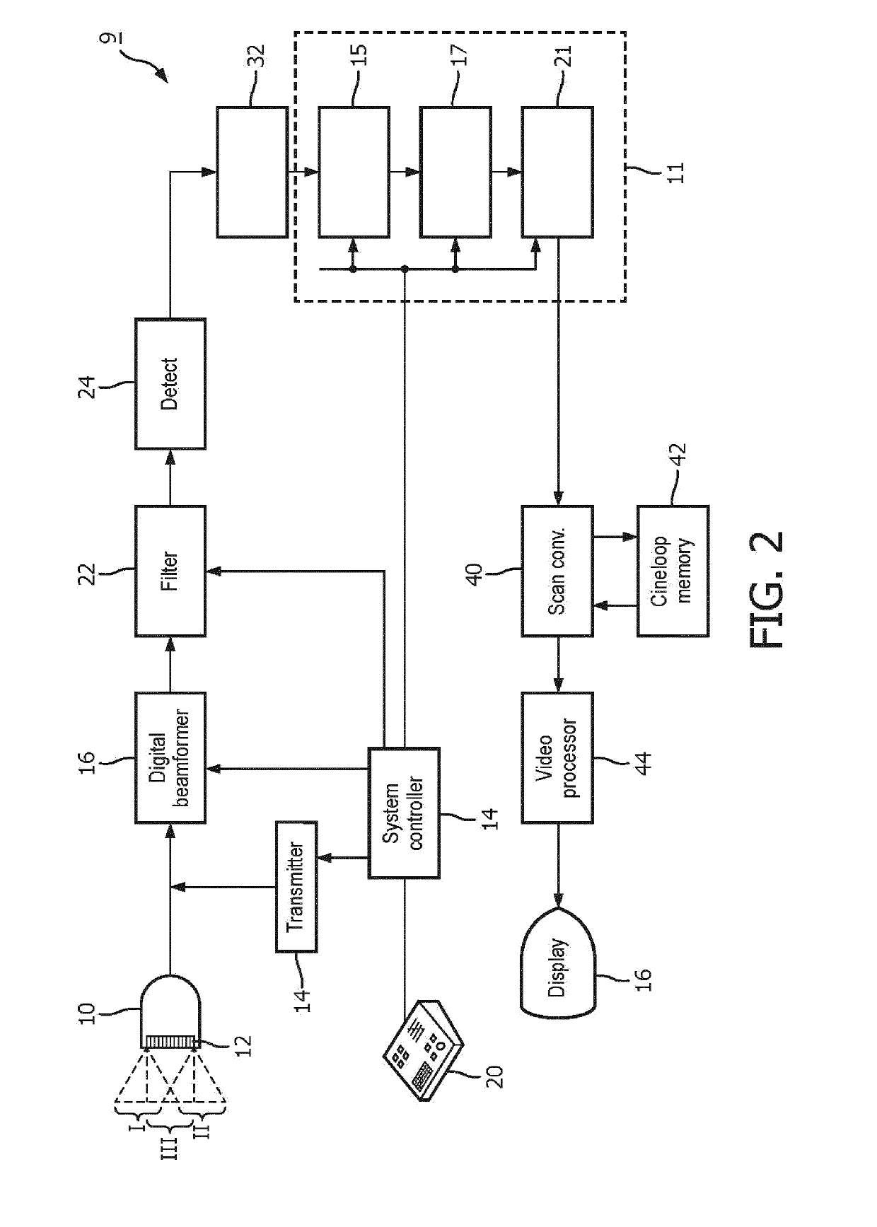
[0069]The apparatus of the present invention can be used either with 2D or 3D ultrasound imaging systems and probes. FIG. 2 shows a schematic block diagram of the ultrasound imaging system 9, which can be used in a combination with an apparatus 11 of the present invention. The ultrasound imaging system 9 has a probe 10 including an ultrasound transducer array 12 arranged to steer (transmit) ultrasound beams at different angles denoted by the dashed rectangle and parallelograms over a volumetric region. In this example, three groups of scanlines forming a plurality of ultrasound images are indicated in the drawing, labeled I, II and III with each group being steered at a different angle relative to the probe or emitting surface of the array 12. These ultrasound image data can be acquired using either a mechanically steered array or by means of electronic ultrasound beam steering. The transmission of the beams is controlled by a transmitter 14 which controls the phasing and time of ac...


PUM


Abstract

The apparatus is adapted to detect a tip of an interventional tool based on at least two ultrasound images reconstructed for different beam steering angles within a volumetric region comprising said tool. The apparatus comprises an image processing unit, which includes a tip detection module configured to perform a tip tool detection procedure. The tip tool detection procedure involves identifying shadow regions of the tool in the at least two ultrasound images and calculating the position of the tip of the tool within the volumetric region.

Description

FIELD OF THE INVENTION[0001]The present invention relates to an apparatus and method for detecting a tool including a tip of the tool, and in particular to an apparatus and method for imaging an interventional tool using images obtained by ultrasound imaging.BACKGROUND OF THE INVENTION[0002]Ultrasound imaging is one of the most popular imaging systems for tool guidance applications. Ultrasound imaging may be used to image tools such as needles, laparoscopes, stents, and radioactive seeds used for brachytherapy. For example, ultrasound imaging may be used for needle guidance in anesthesiology, tissue ablation or for biopsy guidance, since needles are used to take tissue samples, and to deliver medicine or electrical energy to the targeted tissue inside a patient's body. During these procedures, visualization of the needle and its tip is very important in order to minimize risk to the patient and improve health outcomes.[0003]Typically, 2D ultrasound guidance is used to visualize an i...

Claims


Application Information

Patent Timeline
Patent Type & Authority Applications(United States)
IPC IPC(8): A61B34/20A61B8/08A61B8/00A61B8/14G01S15/89G06T7/00
CPCA61B34/20A61B8/0841A61B8/466A61B8/145G01S15/8915G01S15/8993G06T7/0012A61B2017/3413A61B2034/2063A61B2034/2065A61B2090/378G06T2207/10136G06T2207/20224A61B8/4461A61B8/483G06T5/50G10K11/34G06T7/73G01S15/8995G06T2207/10132G06T2207/30021G06T7/0014
Inventor KUENEN, MAARTEN PETRUS JOSEPHMIHAJLOVIC, NENADPOURTAHERIAN, ARASH
Owner KONINKLJIJKE PHILIPS NV
Why Eureka
Try Eureka