Broadband antenna

a broadband antenna and antenna technology, applied in the direction of resonant antennas, non-resonant long antennas, radiating elements structural forms, etc., can solve the problem that the input impedance of the antenna matching circuit cannot be adjusted to achieve the required impedance match, and the circuit does not support multi-level resonance, etc. problem, to achieve the effect of superior antenna characteristics including impedance match and operating bandwidth, smooth antenna variation, and superior antenna characteristics

a broadband antenna and antenna technology, applied in the direction of resonant antennas, non-resonant long antennas, radiating elements structural forms, etc., can solve the problem that the input impedance of the antenna matching circuit cannot be adjusted to achieve the required impedance match, and the circuit does not support multi-level resonance, etc. problem, to achieve the effect of superior antenna characteristics including impedance match and operating bandwidth, smooth antenna variation, and superior antenna characteristics

US20080258980A1Inactive Publication Date: 2008-10-23ADVANCED CONNECTEK INC

Image

  • Broadband antenna
  • Broadband antenna
  • Broadband antenna

Examples


Embodiment Construction

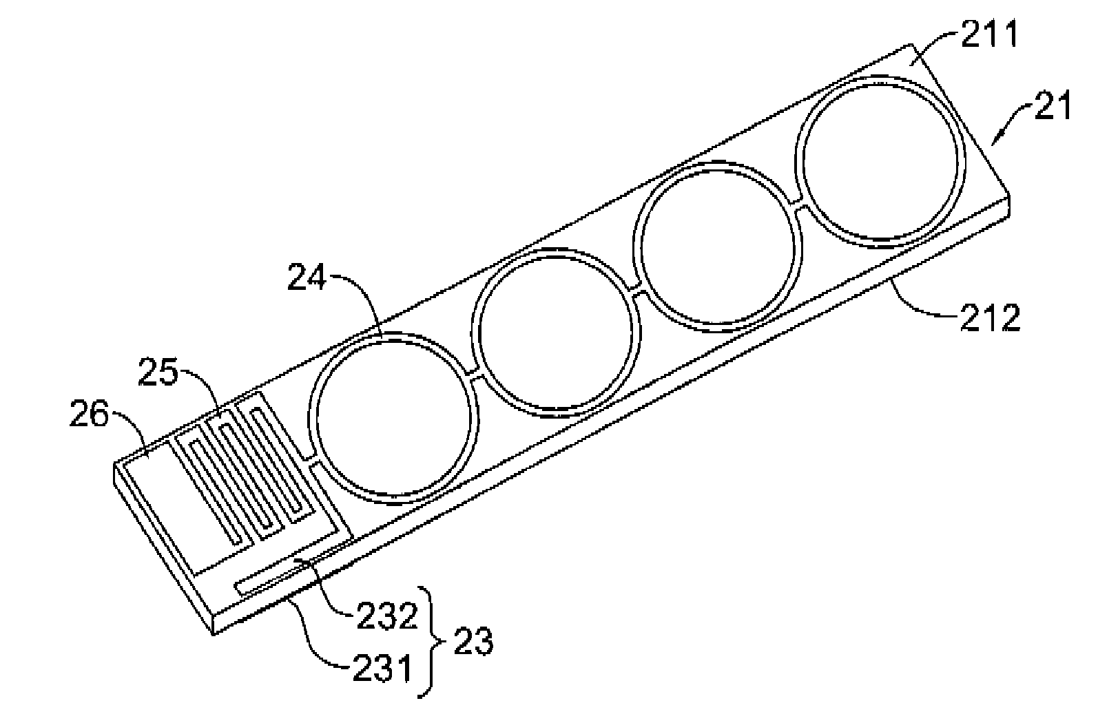
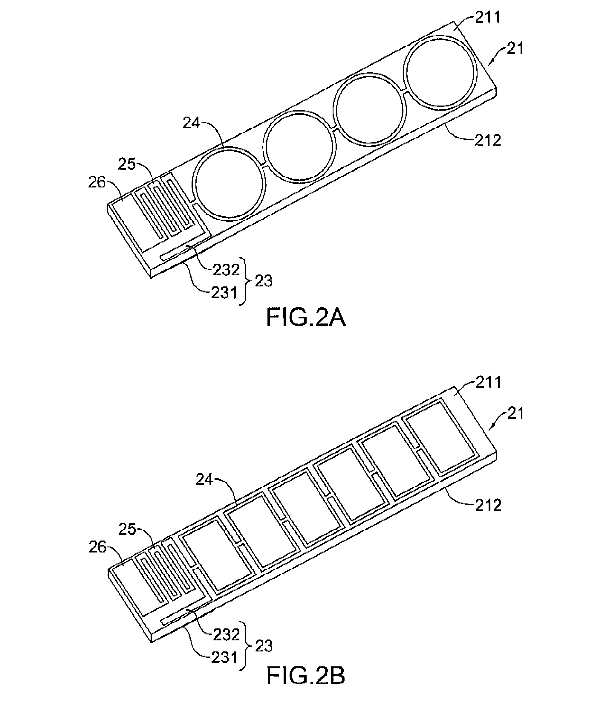
[0021]With reference to FIGS. 2A to 2C, a broadband antenna in accordance with the present invention comprises a substrate (21), a coupling conductor (23), a conductor string, a ground conductor (25) and a ground plane (26).

[0022]The substrate (21) has a top surface (211) and a bottom surface (212) with a thickness, a length and a width. The thickness is about 0.5 millimeter (mm), the length is about 109 mm and the width is about 10 mm.

[0023]The coupling conductor (23) is equivalent to a capacitive element and has a first coupling member (231) and a second coupling member (232) being separated by a distance.

[0024]The first coupling member (231) is formed on the bottom surface (212) of the substrate (21) and has a length and a width being approximately 19 mm and 1 mm respectively. The second coupling member (232) is formed on the top surface (211) of the substrate (21) and has a length and a width being approximately 17 mm and 1 mm respectively. The distance between the first couplin...


PUM


Abstract

A broadband antenna has a substrate, a coupling conductor, a conductor string, a ground conductor and a ground plane. The coupling conductor has a first coupling member and a second coupling member being separated from each other. The conductor string and the ground conductor are connected to the second coupling member. The conductor string extends along a direction opposite to the second coupling member. The ground conductor is connected to the ground plane. The broadband antenna uses the coupling conductor and the ground conductor to adjust input impedance for impedance match. The conductor string functions as a multi level resonance circuit to increase impedance bandwidth.

Description

BACKGROUND OF THE INVENTION[0001]1. Field of the Invention[0002]The present invention relates to an antenna, and more particularly to a broadband antenna that has multiple radiation conductors connected in series as a conductor string.[0003]2. Description of Related Art[0004]Wireless Communication technologies develop rapidly in recently years and various wireless products are marketed popularly. One of most important components in wireless product is an antenna. The design of the antenna requires stricter criteria than the past in size and performance aspects. Taking account of the appearance and size of wireless products, miniature antennas for those products are necessary. Accordingly, the monopole antenna utilizing a metallic ground plane to replace a negative radiator is developed. The monopoly antenna achieves superior radiation effects with a shorter length, i.e. a half of that of a dipole antenna. Subsequent to the monopole antenna, fabricators develop a folded monopole ante...

Claims


Application Information

Patent Timeline
23 Oct 2008
Publication
US20080258980A1
IPC
H01Q9/04
CPC
H01Q1/242; H01Q1/36; H01Q1/38
Inventors
CHEN, WEN-SHYANG; CHANG, YAO-YUAN