Pellicle, lithographic apparatus and device manufacturing method

Active Publication Date: 2008-10-23
ASML NETHERLANDS BV
View PDF15 Cites 34 Cited by
  • Summary
  • Abstract
  • Description
  • Claims
  • Application Information

AI Technical Summary

Benefits of technology

[0012]According to an aspect of the invention, there is provided a device manufacturing method comprising intercepting a beam of EUV radiation with a pellicle, enhancing the spectral purity of the beam of EUV radiation w

Problems solved by technology

A drawback of having such a rather high Xe pressure is that Xe gas absorbs EUV radiation

Method used


Image

  • Pellicle, lithographic apparatus and device manufacturing method
  • Pellicle, lithographic apparatus and device manufacturing method
  • Pellicle, lithographic apparatus and device manufacturing method

Examples


Embodiment Construction

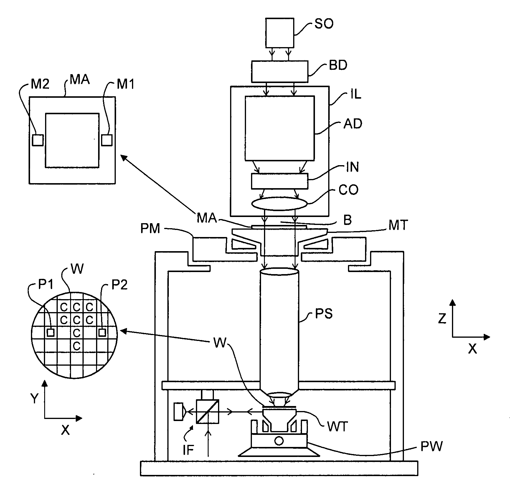
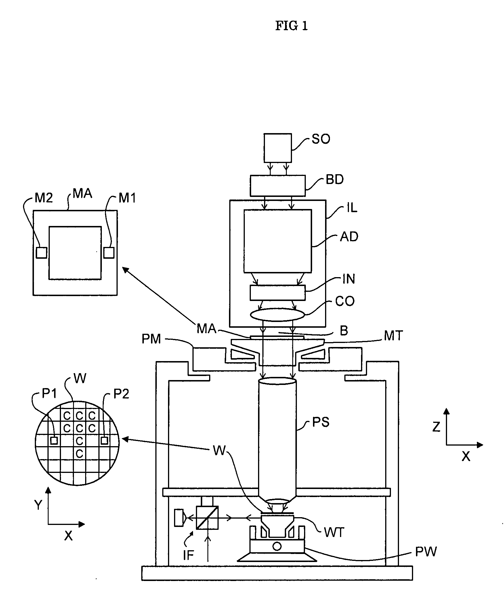
[0020]FIG. 1 schematically depicts a lithographic apparatus according to one embodiment of the invention. The apparatus comprises: an illumination system (illuminator) IL configured to condition a radiation beam B, notably Extreme Ultra Violet (EUV) radiation; a support structure (e.g. a mask table) MT constructed to support a patterning device (e.g. a mask) MA and connected to a first positioner PM configured to accurately position the patterning device in accordance with certain parameters; a substrate table (e.g. a wafer table) WT constructed to hold a substrate (e.g. a resist-coated wafer) W and connected to a second positioner PW configured to accurately position the substrate in accordance with certain parameters; and a projection system (e.g. a reflective projection system) PS configured to project a pattern imparted to the radiation beam B by patterning device MA onto a target portion C (e.g. comprising one or more dies) of the substrate W.

[0021]The illumination system may i...


PUM


Abstract

A pellicle for integrated circuit equipment operating in an EUV range includes a multi-layered structure of alternating layers. The pellicle is constructed and arranged to reflect or absorb undesired radiation and to intercept debris to enhance the spectral purity of a radiation beam.

Description

FIELD[0001]The present invention relates to a pellicle, a lithographic apparatus and a method for manufacturing a device.BACKGROUND[0002]A lithographic apparatus is a machine that applies a desired pattern onto a substrate, usually onto a target portion of the substrate. A lithographic apparatus can be used, for example, in the manufacture of integrated circuits (ICs). In that instance, a patterning device, which is alternatively referred to as a mask or a reticle, may be used to generate a circuit pattern to be formed on an individual layer of the IC. This pattern can be transferred onto a target portion (e.g. comprising part of, one, or several dies) on a substrate (e.g. a silicon wafer). Transfer of the pattern is typically via imaging onto a layer of radiation-sensitive material (resist) provided on the substrate. In general, a single substrate will contain a network of adjacent target portions that are successively patterned. Known lithographic apparatus include so-called stepp...

Claims


Application Information

Patent Timeline
IPC IPC(8): G03B27/42
CPCG03F1/0092G03F1/84G03F7/70191G03F7/70916G03F7/70958G03F7/70983G03F1/62
Inventor BANINE, VADIM YEVGENYEVICHBLEEKER, ARNO JAN
Owner ASML NETHERLANDS BV
Why Eureka
Try Eureka