System and method for forming a non-linear channel within a molded component

a technology of molded components and channels, which is applied in the field of system and method for forming channels within molded plastic parts, can solve the problems of increasing manufacturing costs and time, and the inability of rigid straight core pins to form such channels, and achieve the effect of efficient forming channels through molded components

Inactive Publication Date: 2008-10-23
ILLINOIS TOOL WORKS INC
View PDF4 Cites 11 Cited by
  • Summary
  • Abstract
  • Description
  • Claims
  • Application Information

AI Technical Summary

Benefits of technology

[0005]Embodiments of the present invention provide a system and method that efficiently form curved channels through molded components.
[0012]Certain embodiments of the present invention provide a method of forming a non-linear channel within a molded component. The method may include forming a malleable core-out pin, curving the malleable core-out pin to conform to a shape of a curved channel to be formed within the molded component, positioning the curved, malleable core-out pin within a molding chamber of a forming device, disposing or dispensing liquid plastic into the molding chamber around the curved, malleable core-out pin, allowing the liquid plastic to solidify and cool to form the molded component, removing the molded component from the molding chamber after the allowing step, and extracting the curved, malleable core-out pin from the molded component after the removing step to form the non-linear channel within the molded component.

Problems solved by technology

The rigid straight core pin is unable to form such a channel, particularly in a plastic part.
Such a process increases manufacturing costs and time.
Additionally, the abrupt, straight edged angle formed by multiple rigid pins may snag items threaded through the channel.

Method used


Image

  • System and method for forming a non-linear channel within a molded component
  • System and method for forming a non-linear channel within a molded component
  • System and method for forming a non-linear channel within a molded component

Examples


Embodiment Construction

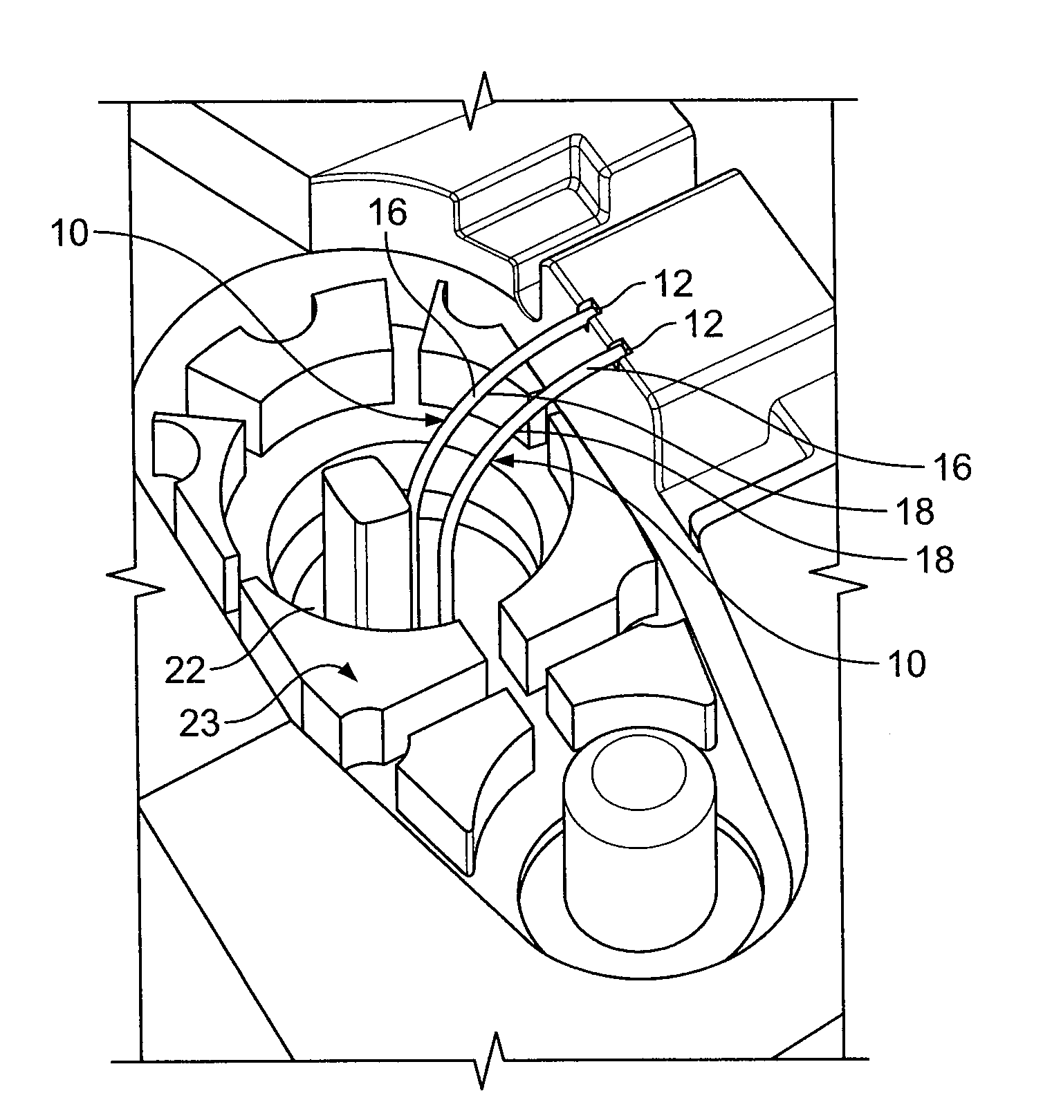
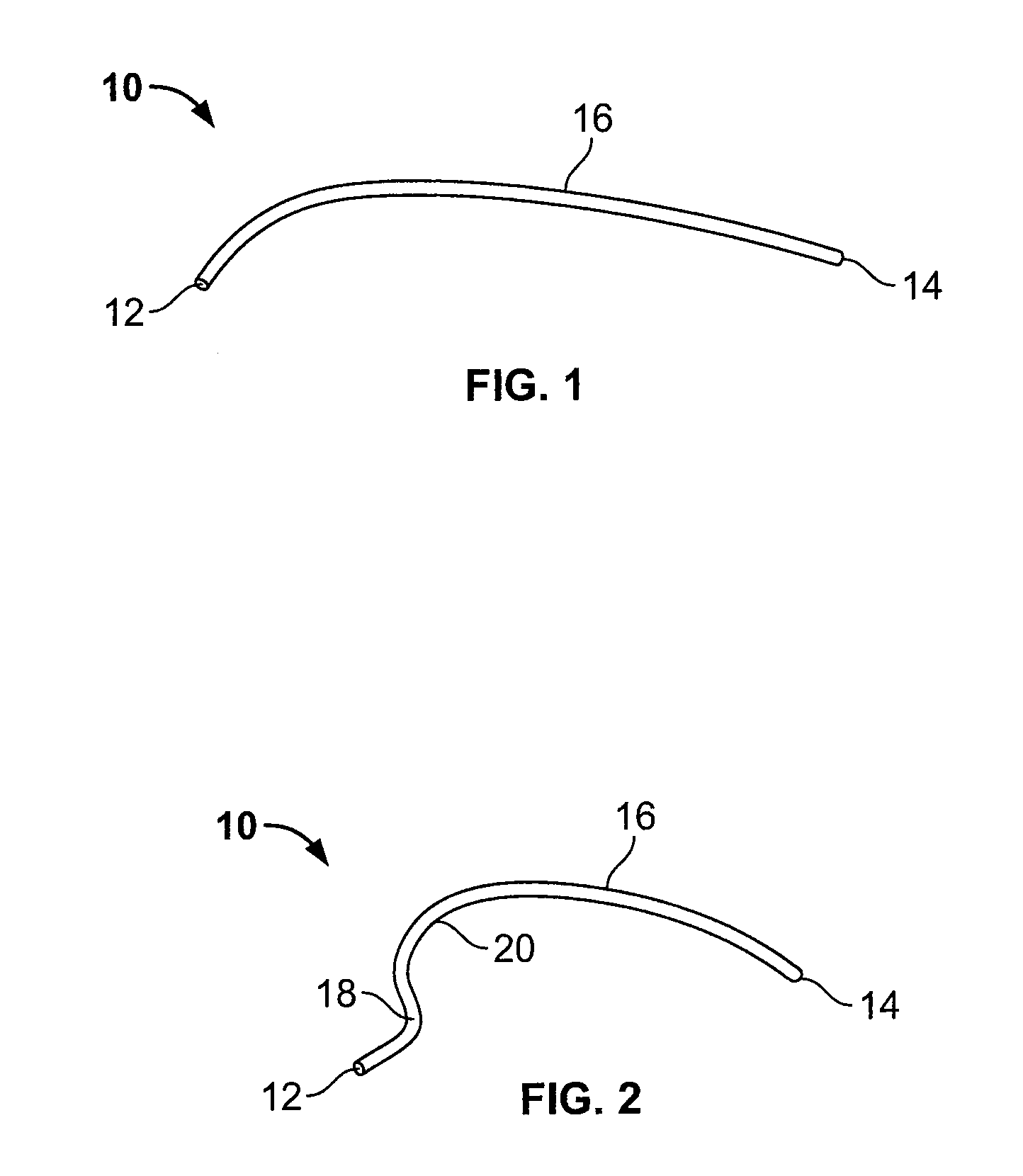
[0023]FIG. 1 illustrates an isometric view of a core-out pin 10 in a first configuration according to an embodiment of the present invention. The core-out pin 10 is a malleable piece of metal. For example, the core-out pin may be a rolled piece of soft steel, gold or aluminum wire. The core-out pin 10 includes a first end 12 connected to a second end 14 through a rolled and stretched wire 16. The core-out pin 10 does not necessarily need to be a piece of rolled and stretched wire. Instead, the core-out pin 10 may be formed through any process that ensures malleability. That is, the core-out pin 10 is formed to be a malleable cylinder having a particular gauge, diameter, circumference and the like, depending on the size of a channel to be formed. For instance, if a channel of relatively large diameter is desired, the core-out pin 10 is formed accordingly. Because the core-out pin 10 is malleable, it may be bent and shaped into various curved configurations.

[0024]FIG. 2 illustrates an...


PUM

PropertyMeasurementUnit
softaaaaaaaaaa
shapeaaaaaaaaaa
hardaaaaaaaaaa

Abstract

Embodiments of the present invention provide a system and method for forming a non-linear channel through a molded component. The system includes a forming device having a molding chamber, and a malleable core-out pin positioned within the molding chamber. The malleable core-out pin includes at least one curve. Liquid plastic is injected into the molding chamber and flows around the malleable core-out pin to form the molded component. After the plastic solidifies and cools, the malleable core-out pin is removed from the molded component to form the non-linear channel through the molded component.

Description

RELATED APPLICATIONS[0001]This application relates to and claims priority benefits from U.S. Provisional Patent Application No. 60 / 925,347 entitled “Core-Out Apparatus and Method,” filed Apr. 19, 2007, which is hereby incorporated by reference in its entirety.FIELD OF THE INVENTION[0002]Embodiments of the present invention generally relate to a system and method for forming a channel within a molded plastic part, and more particularly to a system and method that are configured to form a non-linear channel within a molded plastic component.BACKGROUND OF THE INVENTION[0003]In order to form a hole or channel within a molded part, a rigid straight core pin is typically used. The pin itself is usually formed of hard steel. During a forming process, after plastic flows around the rigid core pin, the plastic cools and solidifies. When the core pin is pulled out of the part, a linear channel defined by the rigid straight core pin is formed through the solidified plastic.[0004]In various app...

Claims


Application Information

Patent Timeline
Patent Type & Authority Applications(United States)
IPC IPC(8): B29C33/12
CPCB29C33/76Y10T428/22B29C45/4478
Inventor SMITH, RONALD M.
Owner ILLINOIS TOOL WORKS INC
Why Eureka
Try Eureka