
Detection And Analysis System For Protein Array

a protein array and analysis system technology, applied in the field of detection and analysis system for protein arrays, can solve the problems of inability to easily construct a system using such a photodetector, and the cost of two-dimensional photodetectors which can detect ultraviolet light is extremely high, so as to achieve the effect of inexpensive and readily available, inexpensive and readily availabl

Inactive Publication Date: 2008-10-23
NAT INST OF ADVANCED IND SCI & TECH
View PDF8 Cites 9 Cited by
  • Summary
  • Abstract
  • Description
  • Claims
  • Application Information

AI Technical Summary

Benefits of technology

[0014]The present inventors have conducted intensive investigations, taking the above-mentioned problems into consideration, for developing a system for detecting or analyzing the interaction between a protein and a protein and / or another substance by using a protein array utilizing equipment which does not require labeling the protein with a fluorescent dye or the like and is inexpensive and readily available.
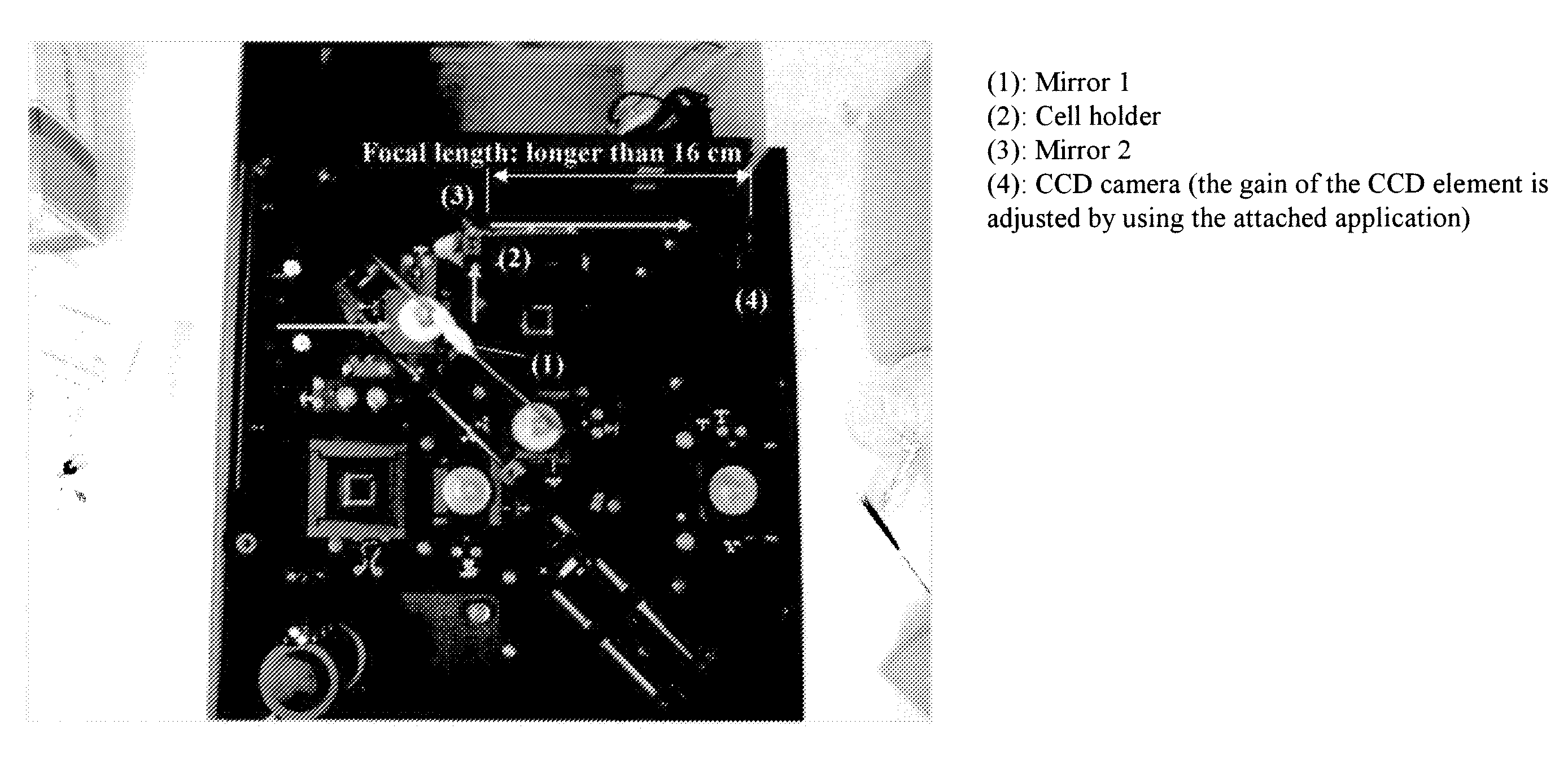
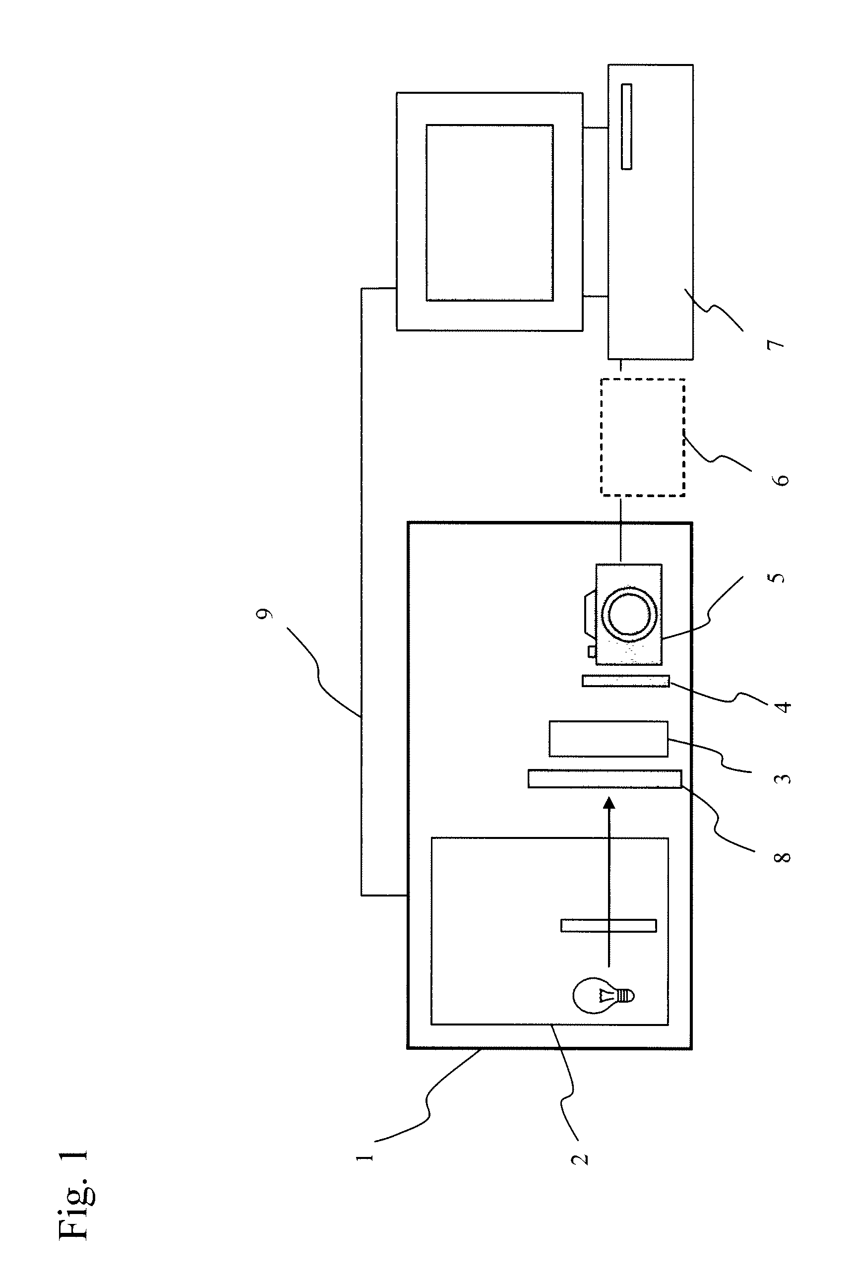
[0015]In conventional methods, characteristically, a protein is immobilized on an array substrate in femto- to picomole quantities for detecting a very small amount of an analyte; a label such as a fluorescent dye is used for detecting a very small amount of protein; or a system which needs a specific apparatus such as SPR is used. The present inventors completed a method for immobilizing a protein on an array substrate at a high density with controlled orientation (JP Patent Nos. 2517861, 2990271, and 3047029, JP Patent Publication (Kokai) No. 2003-344396A, and so on). According to this method, a protein can be immobilized on a substrate in the order of nmol / cm2 which is ten to hundred times greater than the conventional amount. The present inventors have found the fact that this protein array to which a protein is immobilized at a high density allows to measure the protein on the array by measuring optical activity of the protein with a spectrophotometer which is widely used and is relatively inexpensive, without labeling the protein with a fluorescent dye and using an expensive apparatus. In other words, since a large amount of a protein is immobilized on a substrate at a high density, when the immobilized protein is irradiated with light having a wavelength which is absorbed by the protein or a substance which interacts with the immobilized protein, the irradiated light is absorbed by the protein or the substance interacts with the protein on the array. The light absorbed by the immobilized protein or the substance which interacts with the protein can be determined by measuring the intensity of the transmitted light without being absorbed by the protein or the substance. That is, the present inventors have found the fact that a protein on an array or a substance which interacts with the protein can be directly measured by utilizing its optical activity. In particular, since proteins absorb ultraviolet light, the ultraviolet light not absorbed by a protein can be measured as light transmitted through the array substrate on which the protein is immobilized by using an ultraviolet light-transmissive substrate such as quartz glass. Here, in order to measure the transmission of light at each protein spot immobilized on an array substrate at once, it is desirable to use a two-dimensional photodetector such as a CCD. However, a two-dimensional photodetector which can detect ultraviolet light is extremely expensive. Therefore, a system using such a photodetector cannot be readily constructed. Hence, the present inventors have completed the present invention by converting ultraviolet light transmitted through a substrate on which a protein is immobilized into visible light with an ultraviolet-visible light converting device such as fluorescent glass so that a CCD which is inexpensive and readily available can be used.
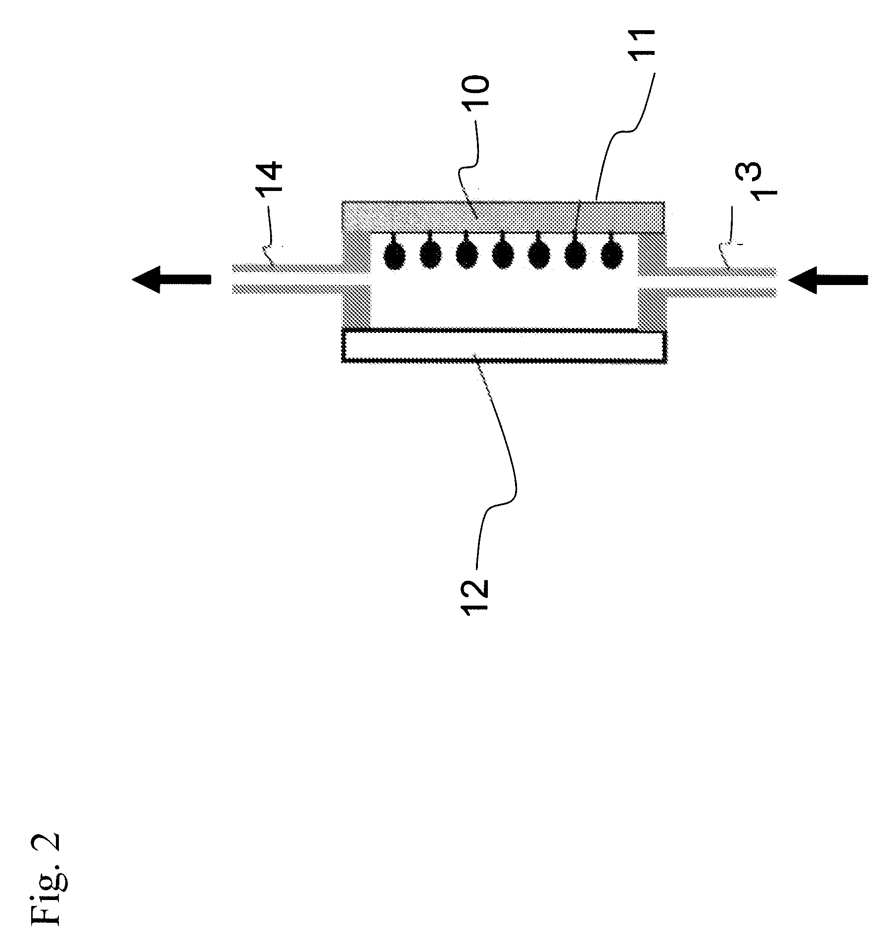
[0017]In the protein array used in the present invention, a protein is immobilized on a light-transmissive substrate at a high density with controlled orientation. Therefore, the light absorbed by the protein can be determined by irradiating the substrate with light and measuring light transmitted through the substrate. Further, the amount of the protein on the protein array can be measured using this light absorption. Therefore, a substance labeled with a fluorescent dye or the like is not necessary for the detection, unlike conventional methods. In addition, the amount of a protein on the protein array can be directly determined by measuring optical activity of the protein. Further, in the present invention, since ultraviolet light, visible light, or infrared light is measured, the amount of a protein on a protein array can be readily measured using a spectrophotometer which is widely used. In particular, a protein on the protein array can be precisely measured using ultraviolet absorption which is generally carried out as a method for quantifying proteins. Furthermore, a protein at each spot on the protein array can be rapidly measured at once by using a two-dimensional photodetector, such as a CCD, as the light-detecting means. In addition, a CCD for digital cameras, which is inexpensive and readily available, can be adopted by using an ultraviolet light-transmissive substrate and fluorescent glass and the like capable of converting ultraviolet light into visible light. Consequently, the cost for constructing a system is low.

Problems solved by technology

However, a two-dimensional photodetector which can detect ultraviolet light is extremely expensive.
Therefore, a system using such a photodetector cannot be readily constructed.

Method used


Image

  • Detection And Analysis System For Protein Array
  • Detection And Analysis System For Protein Array
  • Detection And Analysis System For Protein Array

Examples


examples

[0075]The present invention will be specifically described with reference to the following examples, but the present invention is not limited by these examples.

[0076]In this example, a base material for a protein array was prepared by forming a thin sheet of a polyacrylamide gel containing a polymer having an amino group on a surface of quartz glass. Since this base material substantially did not absorb light in the wavelength range of visible light and ultraviolet light (transparent), the optical activity of a protein present in the gel was able to be directly detected. In other words, an immobilized protein and a protein which interacted with the immobilized protein were able to be detected / analyzed by an optical method, without a specific labeling process.

[0077]In this example, a green fluorescent protein (SEQ ID No:1) and dihydrofolate reductase (SEQ ID NO:4) were immobilized on this base material for a protein array. Since the green fluorescent protein was green under natural l...


PUM


Abstract

To provide a method for detecting a protein by immobilizing a protein on a protein array substrate at a high density with controlled orientation, irradiating the immobilized protein with ultraviolet light, visible light, or infrared light, and measuring the light not absorbed by the protein and further analyzing an interaction between the protein on the substrate and another protein and / or a compound other than proteins, a system used for the method, and to provide a protein array suitable for the system. A system including a protein array in which a protein is immobilized in aligned position on a light-transmissive substrate at a high density, a light-irradiating means, and a light-detecting means and being for detecting or analyzing a protein on the protein array and / or a compound which is other than proteins and interacts with the immobilized protein, wherein the protein array is irradiated with light by the light-irradiating means, and the light transmitted through the protein array is measured by the light-detecting means for detecting the light absorption of the protein on the protein array and / or the compound which is other than proteins and interacts with the immobilized protein.

Description

TECHNICAL FIELD[0001]The present invention relates to a system for detecting or analyzing a protein on a protein array on which the protein immobilized in aligned position at a high density or an interaction between the protein and another protein and / or a compound other than proteins by measuring ultraviolet, visible, or infrared light absorption of the protein using a spectrophotometer.BACKGROUND ART[0002]A protein array (protein chip) is a technology providing new possibilities as a means for investigating functions of unknown proteins encoded by genes or analyzing complicated interactions among a large number of proteins at once. The protein array is provided by aligning a protein or a peptide on a substrate, and various protein arrays have been reported (see Patent Documents 1 and 2). In protein array technology, a protein is immobilized on an appropriate substrate, the immobilized protein is brought into interaction with another protein or the like, and the interacting spots o...

Claims


Application Information

Patent Timeline
IPC IPC(8): C40B30/10C40B60/12C40B40/10
CPCG01N21/253G01N21/31G01N21/6452G01N33/5308G01N33/54386
Inventor IWAKURA, MASAHIROHIROTA, KIYONORITAKAHASHI, HISASHI
Owner NAT INST OF ADVANCED IND SCI & TECH
Learn More